EasyManuals Logo
Home>Parker>Engine>GVM Series

Parker GVM Series User Manual

Parker GVM Series
82 pages
To Next Page IconTo Next Page
To Previous Page IconTo Previous Page
Page #66 background imageLoading...
Page #66 background image
- 66
18-06-08 PVD3668_GB_GVM_June_2018
3.7.2. Temperature measurement with Linear Positive Temperature Coefficient
sensors :
Motor temperature can also be continuously measured by the drive using an LPTC thermal
sensor (or equivalent) built in to the stator winding. LPTC sensors change their resistance
according to an approximately linear characteristic. The required temperature limits for alarm
and tripping can be set in the drive.
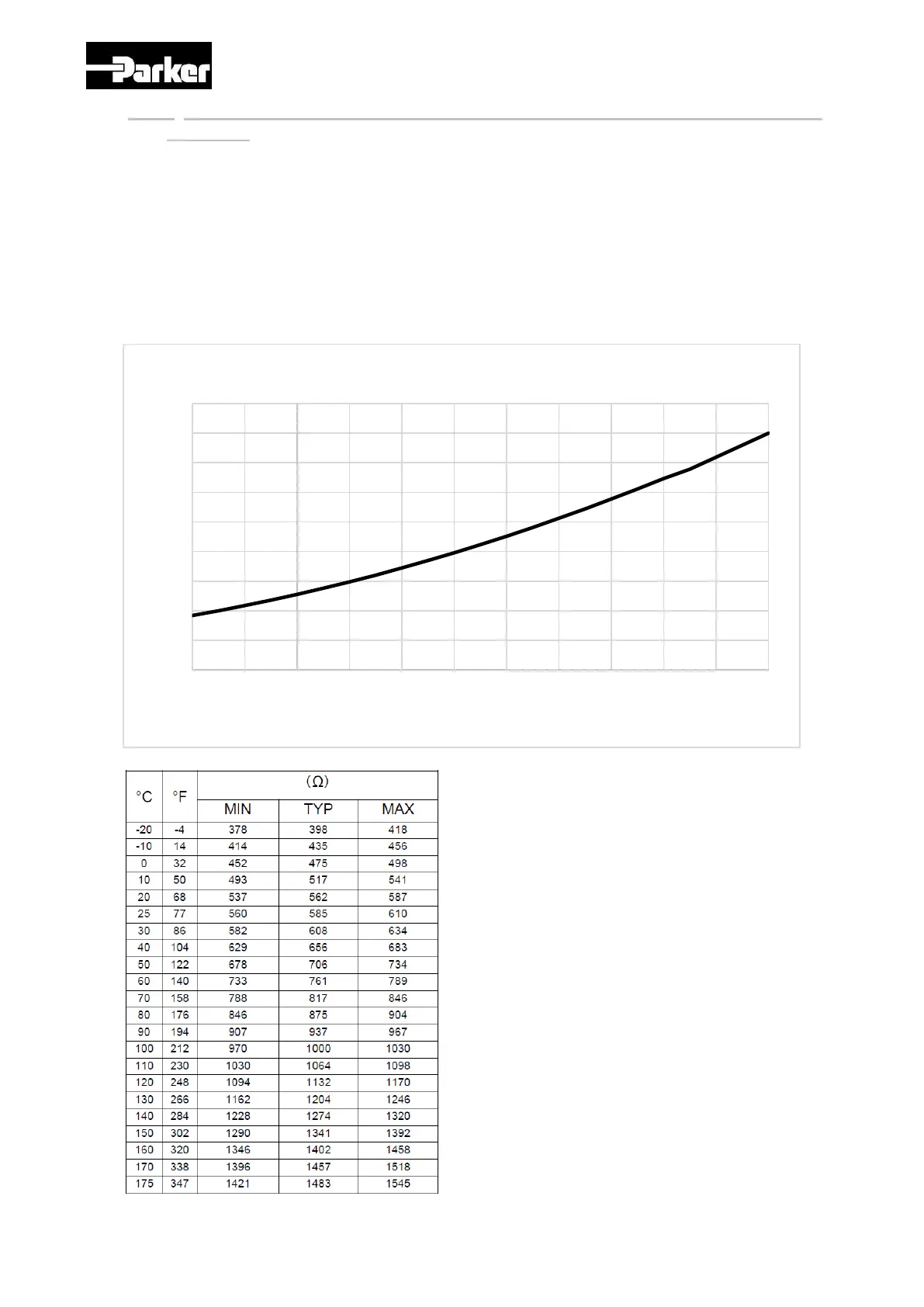
The graph below shows the typical characteristics of the resistance vs temperature,
for a current of 5 mA:
0
200
400
600
800
1000
1200
1400
1600
1800
-40 -20 0 20 40 60 80 100 120 140 160 180
R Ohm
Temperature °C
Linear PTC 600 @ 25°C, 1000 @ 100°C
With resistance measurement, we
can find the correspondant
winding temperature with the
following formula :
T°C = -0.00006*R²+0.2919*R-128

Table of Contents

Questions and Answers:

Question and Answer IconNeed help?

Do you have a question about the Parker GVM Series and is the answer not in the manual?

Parker GVM Series Specifications

General IconGeneral
BrandParker
ModelGVM Series
CategoryEngine
LanguageEnglish

Related product manuals