- 65 –
18-06-08 PVD3668_GB_GVM_June_2018
3.7. Thermal Protection – Positive Temperature Coefficient sensors
Protection against thermal overloading of the motor is provided by three PTC thermistors and
two linear temperature sensors equivalent to KTY84 (one is a redundant spare ; only one is
connected) built into the stator winding as standard. Globally, the thermal sensors, due to
their thermal inertia, are unable to follow very fast winding temperature variations. They
achieve their thermal steady state after a few seconds.
Warning: To protect correctly the motor against very fast overload,
please refer to 3.1.7. Peak current limitations
3.7.1. Alarm tripping with PTC thermistors:
The thermal probes (PTC thermistors) fitted in the servomotor winding trip the electronic
system between 150° and 165° C. When the rated tripping temperature is reached, the PTC
thermistor resistance changes very quickly. This resistance can be monitored by the drive to
protect the motor. As for linear sensor, some delay exists due to the sensor thermal time
constant.
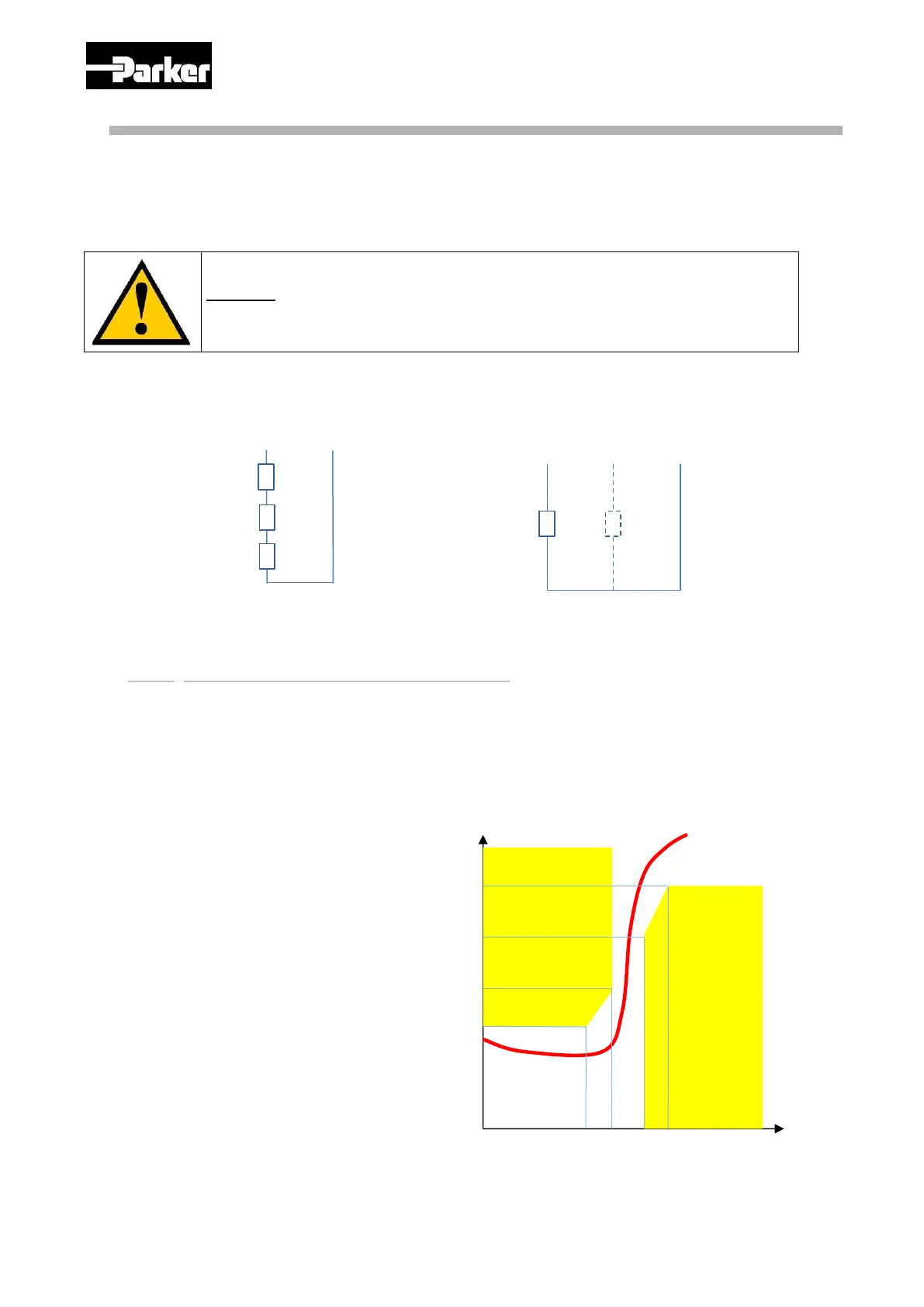
The graph and tab below shows the
PTC thermistor resistance as a
function of temperature
(T
N
is the thermistor nominal
temperature)
 Loading...