- 64 –
18-06-08 PVD3668_GB_GVM_June_2018
3.6.7. Coolant Connections :
GVM142 : Coolant inlet / outlet are ORB-4 SAE J1926-1 with thread 7/16-20 UNF
GVM210 : Coolant inlet / outlet are ORB-8 SAE J1926-1 with thread 3/4-16 UNF
These parts can be provided by Parker as follows :
2 options are available for the GVM fittings :
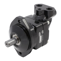
Male Stud Connector Male Stud Elbow
GVM142 : 4F50MXS(S) GVM142 : 4C50MXS(S)
GVM210 : 8F50MXS(S) GVM210 : 8C50MXS(S)
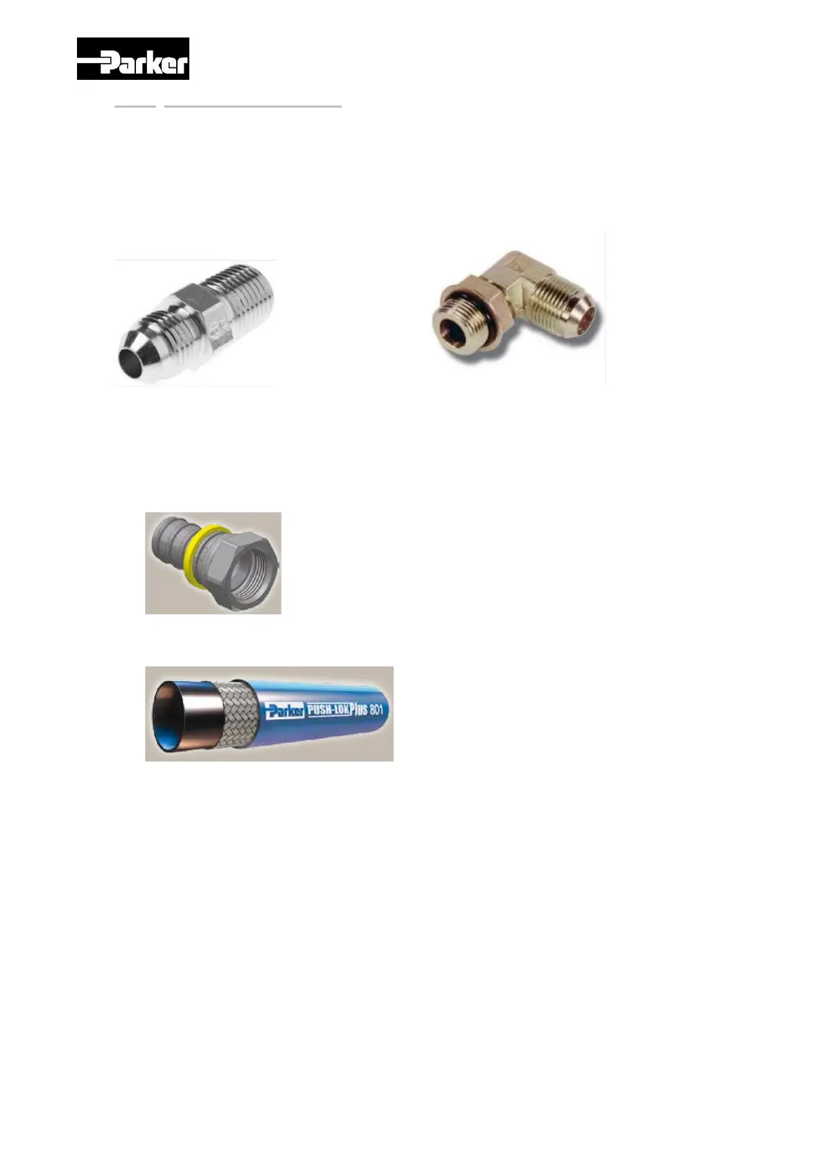
For hoses and their fittings, we advise to use the following :
Push-Lok Fittings
GVM142 : 30682-4-4-SM
GVM210 : 36882-8-8-SM
Push-Lok Hose
With water-glycol or oil up to 85°C :
GVM142 : 801-4-XXX-RL
GVM210 : 801-8-XXX-RL
Where “XXX” stands for
the hose colour
Assembly Instructions :
1. Cut the hose right angled with a sharp knife. If necessary, it is possible to use
a lubricant (water/soap solution with 5% fluid soap and 95% water) for easy
assembly.
2. Insert fitting into hose until first barb is in hose. Place ent of fitting against a
flat object and grip hose approximately 2cm from end and push with a steady
force until end of hose is covered by yellow plastic collar.
 Loading...