EQUIPMENT INSTALLATION 17
Rev E
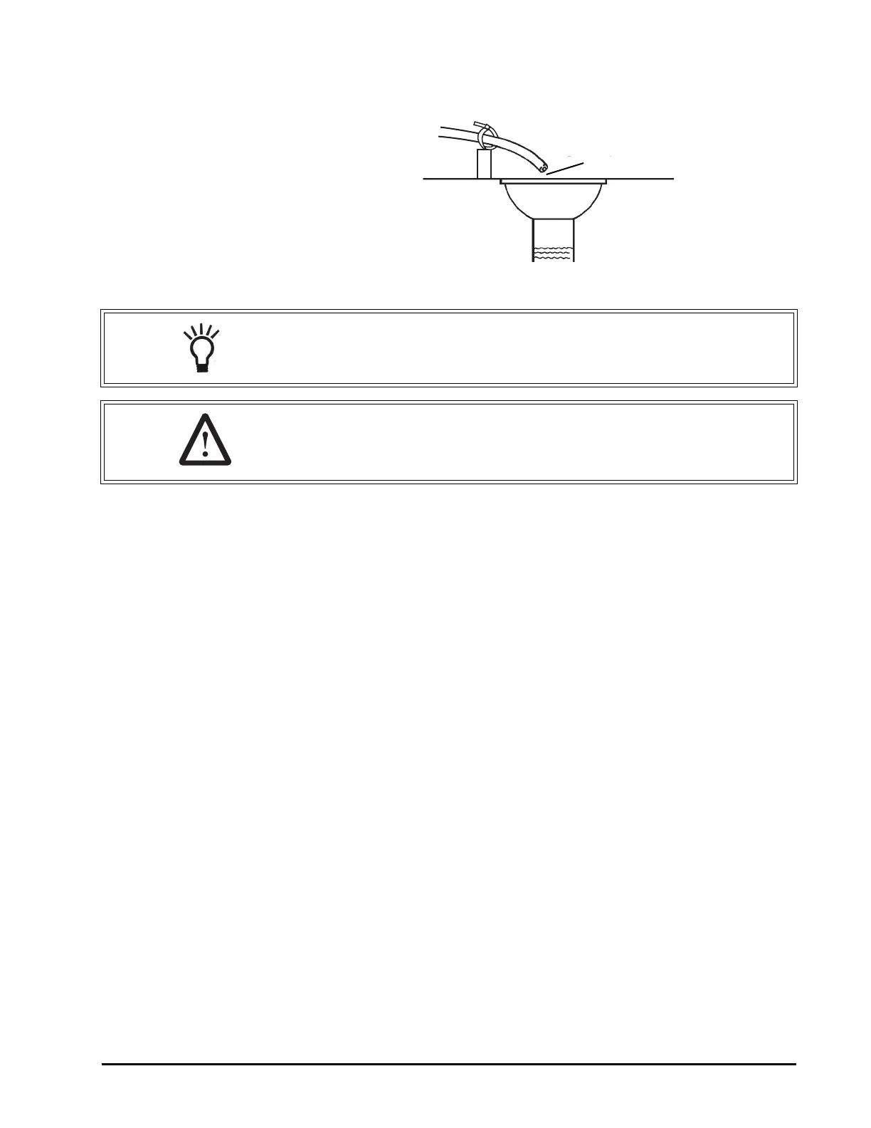
Figure 8
Drain Line Connection
Overflow Line Connection
(not used with 3-cycle filter system)
In the event of a malfunction, the regenerant TANK OVERFLOW will direct
“overflow” to the drain instead of spilling on the floor. This fitting should be on
the side of the cabinet or regenerant tank. Most tank manufacturers include a
post for the tank overflow connector.
To connect the overflow line, locate hole on side of tank. Insert overflow fitting
into tank and tighten with plastic thumb nut and gasket as shown (Figure 9).
Attach length of 1/2-inch (1.3-cm) I.D. tubing (not supplied) to fitting and run to
drain. Do not elevate overflow line higher than overflow fitting.
Do not tie into drain line of control unit. Overflow line must be a direct,
separate line from overflow fitting to drain, sewer or tub. Allow an air gap as
per drain line instructions.
NOTE: Waste connections or drain outlet shall be designed and
constructed to provide for connection to the sanitary waste system through
an air-gap of 2 pipe diameters or 1 inch (22 mm) whichever is larger.
WARNING: Never insert drain line directly into a drain, sewer line, or trap
(Figure 8). Always allow an air gap between the drain line and the
wastewater to prevent the possibility of sewage being back-siphoned into
the conditioner.
 Loading...