2021-09
10
Distance Sensors
Product Description
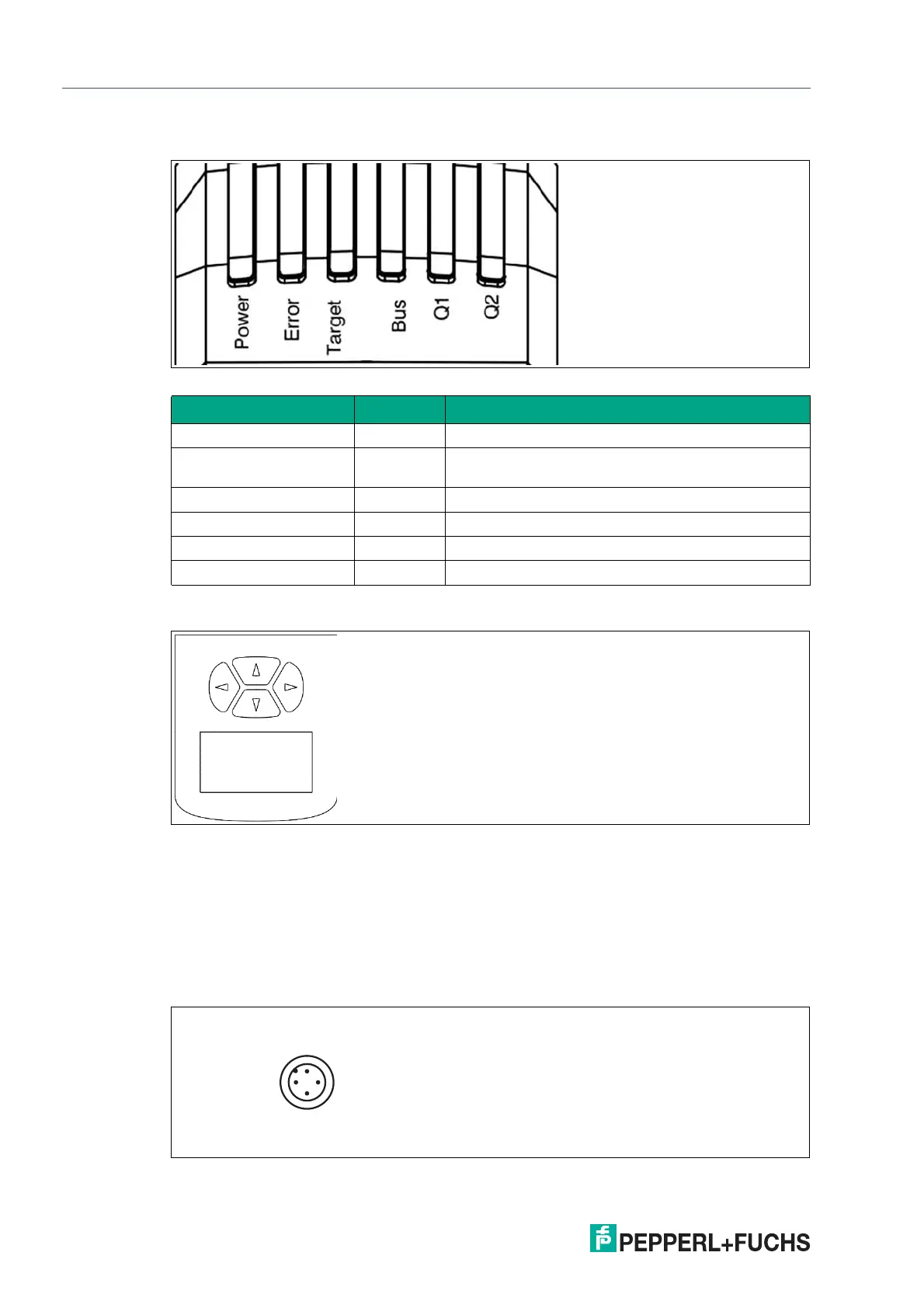
4.3 Indicators and Operating Elements
Figure 4.1 Indicators
Signal indicators at the bottom of the housing do not have a function.
Figure 4.2 Display and arrow keys
4.4 Interfaces and Connections
The following connections are found on all devices:
Power Supply
There is a 4-pin M12 plug on the rear of the housing for connecting the power supply. The fol-
lowing diagram shows the pinout:
Figure 4.3 Power supply connection assignment
Designation Color Description
Power Green Lights up when supplied with operating voltage
Error Red Lights up when there is an error; flashes in the event
of a warning
Target Yellow Lights up when the sensor detects a reflector
Bus Green Signals interface activities
Q1 (No function)
Q2 (No function)
 Loading...