2020-01
30
WCS* Read Head Position Encoding System
SSI Interface (LS3xx*)
5 SSI Interface (LS3xx*)
The read head with SSI interface supports data formats in gray code (LS311) or binary code
(LS310). Data transfer is carried out on the SSI read head at the request of the control panel.
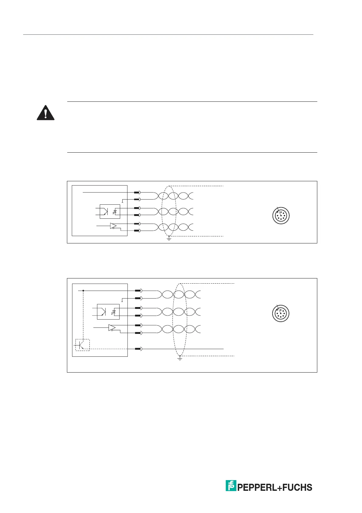
5.1 Electrical Connection and Data Cables
Connection diagram for WCS2B read head
The WCS2B read head with SSI interface is electrically connected via an 8-pin M12 plug.
Figure 5.1 WCS2B, SSI interface
Connection diagram for WCS3B read head
The WCS3B read head with SSI interface is electrically connected via an 8-pin M12 plug.
Figure 5.2 WCS3B, SSI interface
The counterpart of the plug connections, the 8-pin M12 socket, is not included in the scope of
delivery for the respective read head. You can obtain suitable connectors and cables from Pep-
perl+Fuchs, see chapter 12.1.
Caution!
Property damage and system malfunctions due to incorrect pinout
Incorrect assignment of the wire pairs to the respective pins can result in property damage and
system malfunctions.
• Note the assignment of the wire pairs to the pins as shown in the respective wiring dia-
grams.
1
4
6
7
8
53
2
WCS2B-LS3xx
UB 10 ... 30 V
GND
CLK+
1
3
4
2
CLK-
DATA+
5
6
DATA-
Geschwindigkeitsausgang
*
)
I
out
= max. 150 mA
*
)
nur mit Option S, Geschwindigkeitsausgabe
WCS3B-LS3xx
UB 10 ... 30 V
GND
CLK+
1
3
4
2
7
CLK-
DATA+
5
6
DATA-
1
4
6
7
8
53
2

 Loading...


