WCS* Read Head Position Encoding System
RS-485 Interface (LS1xx*, LS2xx*)
2020-01
21
4.3 Data Protocols
Various data protocols and data transmission speeds are available for direct connection of the
read head to the higher-level control panel via a serial communication channel. The data proto-
cols and baud rates are identical for the respective types in the WCS2B and WCS3B read
heads.
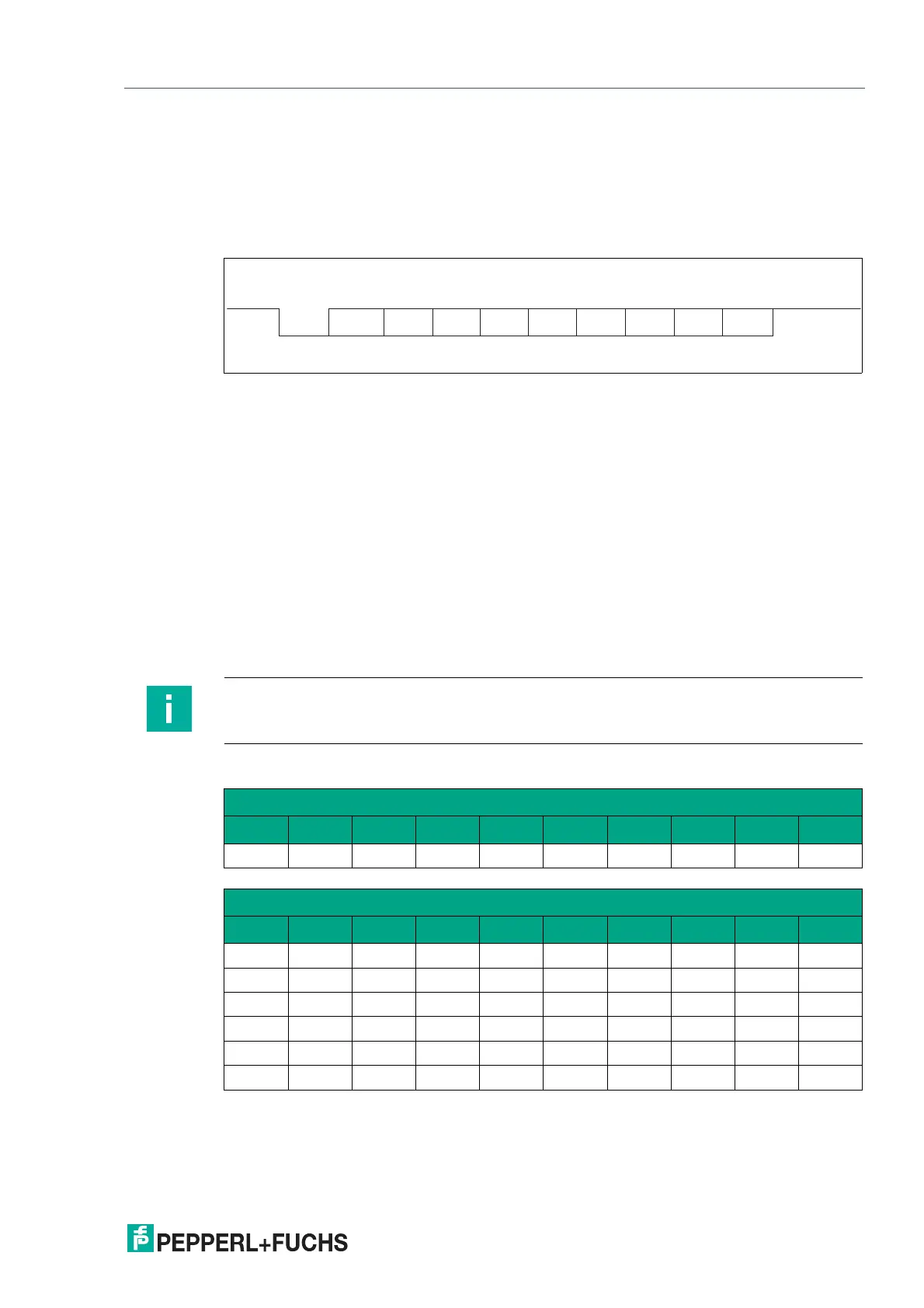
A byte has the following format:
Figure 4.4 Data structure
For data protocols 1 and 2, the eighth data bit is used to distinguish between request bytes and
response bytes. For control panels that do not support direction control via the eighth data bit,
data protocol 3 is available. Read heads with RS-485 interface and data protocol 3 can be sup-
plied as type:
LSxx6 = data protocol 3 with parity (even parity), 9 bits/byte
LSxx7 = data protocol 3 without parity = 8 bits/byte.
Response time
The minimum response time of the read head (start sending the first data bytes from the
response telegram) depends on the internal time sequence of the read head and is 10 ... 180
sec for data protocol 1 and 2.
For data protocol 3, the response time is a byte time + 10 ... 100 sec. The byte time depends
on the baud rate and is calculated from 1/baud rate * 11,000 in sec.
Example: 38.4 kBaud
Byte time = 1/38.4 * 11,000 = 286.5 sec.
Data protocol 1
Start
2
0
2
1
2
6
2
5
2
2
2
3
2
4
2
7
Stop
LSB MSB
Bit 0 1 2 3 4 5 6 7 8
Note
Note the different data protocols for extended read head, see chapter 9.2.
Request byte for read head
Byte Bit 8 Bit 7 Bit 6 Bit 5 Bit 4 Bit 3 Bit 2 Bit 1 Bit 0
1 0 0 0 F0 0 0 A1 A0
Response telegram from the read head
Byte Bit 8 Bit 7 Bit 6 Bit 5 Bit 4 Bit 3 Bit 2 Bit 1 Bit 0
Byte 1 0
OUT ERR A1 A0 DB P18 P17 P16
Byte 2 0
P15 P14 P13 P12 P11 P10 P09 P08
Byte 3 0
P07 P06 P05 P04 P03 P02 P01 P00
Byte 4 0
OUT ERR A1 A0 DB P18 P17 P16
Byte 5 0
P15 P14 P13 P12 P11 P10 P09 P08
Byte 6 0
P07 P06 P05 P04 P03 P02 P01 P00

 Loading...


