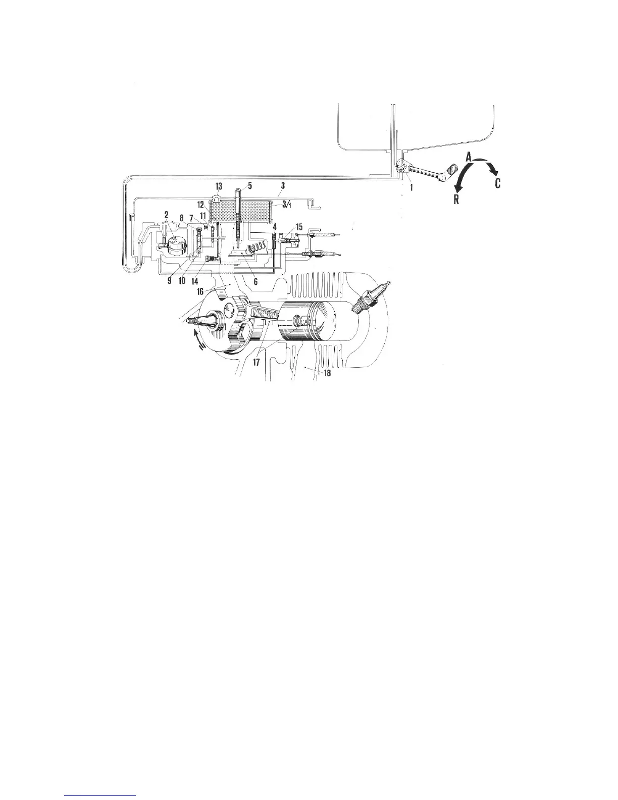
Fig. 9 – Fuel supply and distribution diagram
1. Fuel tap: R) Reserve; A) Open C) Closed; - 2. Float - 3. Air cleaner with carburettor 3/1.
Air filter - 4. Choke device calibrator - 5. Throttle slide set screw - 6. Throttle slide - 7.
Main jet air calibrator - 8. Diffuser air calibrator - 9. Diffuser - 10. Main jet - 11. plow
running jet - 12. Slow running jet air calibrator - 13. Oil cap - 14. Idle air -fuel mixture
adjusting screw - 15. Choke valve - 16. Inlet port - 17. Transfer ports - 18. Exhaust port.
REMOVAL OF ENGINE COWLING
Pull the lever « 1 » on fig. 10 and turn to release it from cowling. Swing the cowling
outwards so that the front locating pin « 2 » is free of its housing.
Lift the cowling upwards from the front pivoting on its rear section: so that the clasp « 3 »
releases from the chassis bracket.
Pull the cowling outwards on the pin «4» so that the latter clears its housing, thus
releasing the cowling. For reassembly carry out the reverse procedure.
 Loading...