MC012C-AS00 TRANSAXLE: HYDRAULIC AND PARK BRAKE SYSTEMS Brake Shoe Installation
2003 Pioneer 1200/1200SE Gasoline Vehicle Maintenance and Service Manual Page 6-13
6
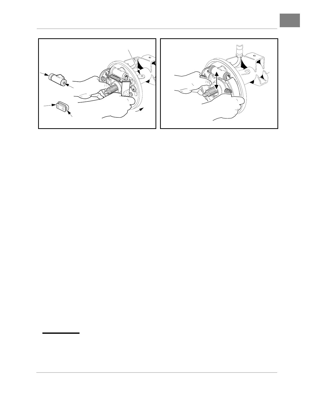
4. Position the bottom tip of the remaining shoe into the mounting block and the top tip into the slot in the
wheel cylinder piston. Attach the free ends of the tensioning springs to the loose shoe and push the shoe
into place (Figure 6-12, Page 6-13).
5. Compress the remaining spring and cup washer (12) onto the pin of the adjuster (3) (Figure 6-19,
Page 6-21) and rotate 90° to secure the brake shoe (Figure 6-4, Page 6-9).
6. After installation, move brake shoes up and down to make sure that they will slide easily approximately
1/4 to 3/8-inch (6.3 to 9.5 mm) without binding (Figure 6-13, Page 6-13).
7. Repeat steps 1 through 6 for the remaining rear wheel if necessary.
8. Install the wheel bolt flange. See following NOTE.
NOTE: Clean splined area in the wheel bolt flange and on the splined end of axle before installation. Use
a small brush to carefully apply a light coat of white lithium NLGI Number 2 grease (Dow Corning
BR2-Plus or equivalent) to both prior to assembly.
8.1. Slide wheel bolt flange (22) onto splined axle (Figure 6-5, Page 6-9).
8.2. Slide the large flat washer (23) onto the end of the axle and up against the wheel bolt flange. See
following NOTE.
NOTE: It is recommended that a light film of white lithium NLGI Number 2 grease (Dow Corning BR2-Plus
or equivalent) be applied to both surfaces of the large washer (23) before the flanged nut (24) is
installed and torqued to specification.
8.3. Attach the flanged nut (24) and tighten to 150 ft-lb (203 N·m).
8.4. Install the locking cap (27) onto the flanged nut (24) and position the locking cap (27) to provide
clear passage for a new cotter pin (25).
8.5. Install a new cotter pin (25) through the locking cap and axle, bending the split ends of the pin to
secure the locking cap (27). See following WARNING.
∆ WARNING
• Make sure to install and bend the cotter pin. Failure to bend the cotter pin could result in the
separation of the wheel bolt flange from the splined end of the axle. Loss of vehicle control
could result, causing severe personal injury.
8.6. Install the rubber boot (26) onto the large washer (23). See following NOTE.
Figure 6-12 Brake Shoe Installation Figure 6-13 Slide Brake Shoes
Lever is present on rear
brake clusters only.
BOTTOM SLOTS
TOP SLOTS
 Loading...