11.22
9926806 R03 - 2015 - 2016 RANGER ETX / 570 2-SEAT 2015 - 2016 RANGER 570 CREW Service Manual
© Copyright Polaris Industries Inc.
RELAYS
OPERATION
The relays assist with fan, ignition coil, fuel pump, brake
light, EFI, headlight, EPS, and rear differential operation.
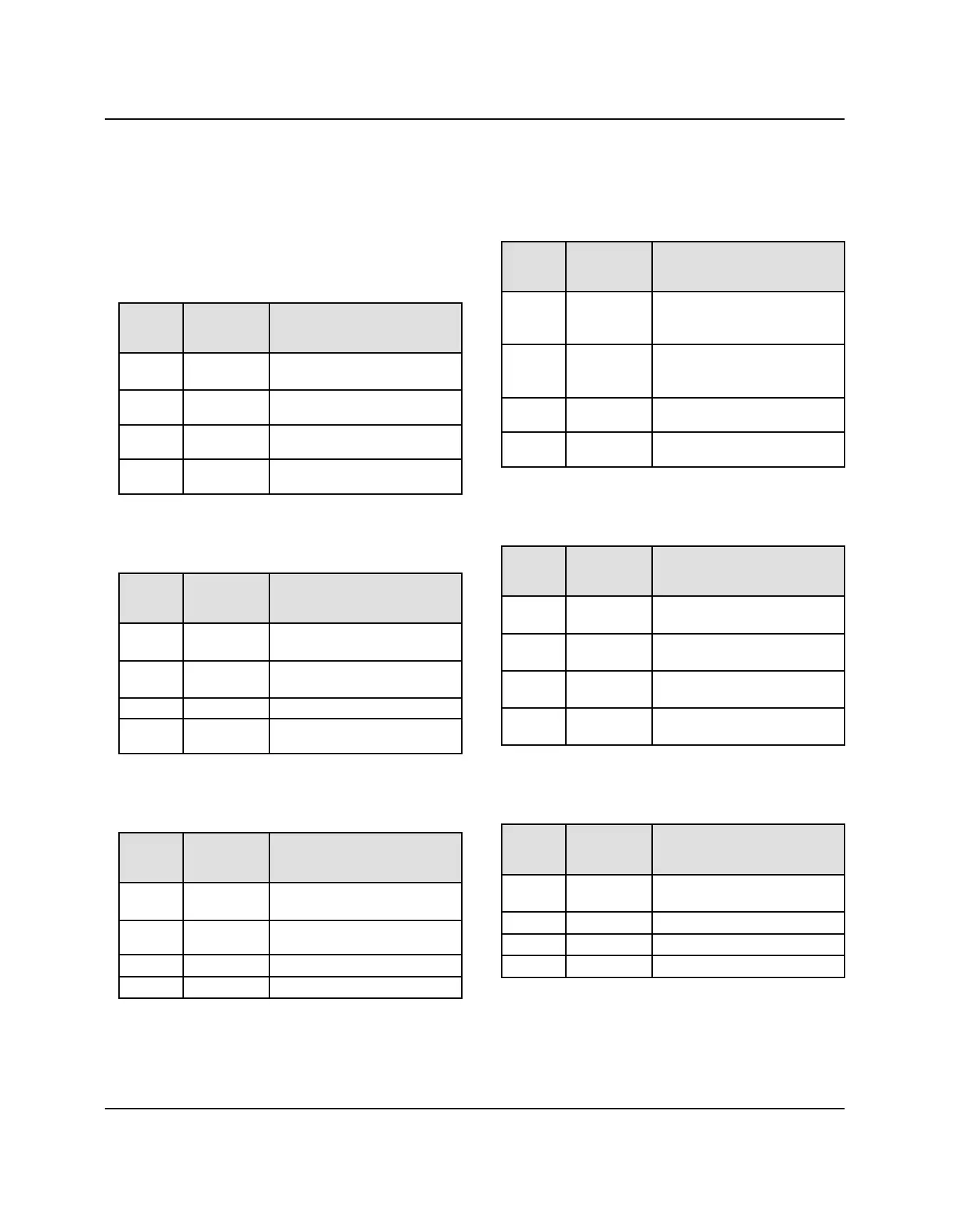
• Fan Relay, controlled by the ECM and engine coolant
temperature sensor, operates the fan motor.
Fan Relay
FUSE
BOX
PIN
WIRE
COLOR OPERATION
9 Red / Dark
Blue
Relay coil 12v from EFI
Splice
10
Orange /
Black
High side 12v from 15A
circuit breaker
13
Orange /
Black
12v output to fan motor
14
Orange /
Black
ECU controlled ground
• Fuel Pump Relay, controlled by the ECM and key
switch, powers the fuel pump.
Fuel Pump Relay
FUSE
BOX
PIN
WIRE
COLOR OPERATION
25
Red / Dark
Blue
Relay coil 12v from EFI
Splice
26 Orange High side 12v from Fuel
Pump fuse
29
Red / Blue Ground, Chassis Rear #1
30
Dark Green
/ Yellow
ECU controlled ground
• Chassis Relay, controlled by the key switch, supplies
B+ to the chassis circuits.
Chassis Relay
FUSE
BOX
PIN
WIRE
COLOR OPERATION
33
Red / Blue Relay coil 12v from EFI
Splice
34 Red
High side 12v from Start
Solenoid
37 Red
12v output to Splice, Chassis
38
Gray ECU controlled ground
• EFI Relay, controlled by the ECM, supplies power to
EFI components and sensors.
EFI Relay
FUSE
BOX
PIN
WIRE
COLOR OPERATION
17 Red
Relay coil 12v from
Unswitched Fused EFI
Splice
18 Red
High side 12v from
Unswitched Fused EFI
Splice
21 Red / Dark
Blue
12v output to EFI Splice #1
22 Dark Green
/ Yellow
ECU controlled ground
• Headlight Relay, controlled by the ignition switch,
supplies power to the headlights.
Headlight Relay
FUSE
BOX
PIN
WIRE
COLOR OPERATION
1 Red /
Yellow
Relay coil 12v from Lights
splice
2
Red /
Yellow
High side 12v from Lights
splice
5
Dark Green 12v output to Headlight Low
Beam splice
6 White / Red
Ignition switch controlled
ground
• EPS Relay (if equipped), controlled by the ignition
switch, provides power to the EPS unit.
EPS Relay
FUSE
BOX
PIN
WIRE
COLOR OPERATION
3 Orange Relay coil 12v from R/S B+
Splice #2
4 Red
High side 12v from EPS fuse
7
Orange 12v output to EPS unit
8 Brown
Chassis ground #2
ELECTRICAL
 Loading...