Jun. 2020 / Rev.0.1 DS-UB40.241-EN All values are typical figures specified at 24Vdc input voltage, 40A output current in
power supply mode at 25°C ambient, no charging and after a 5 minutes run-in time unless otherwise noted.
www.pulspower.com Phone +49 89 9278 0 Germany
The enclosure of the device provides a degree of protection of IP20.
A disconnecting means shall be provided for the input and the battery input of the device.
The device is designed for convection cooling and does not require an external fan. Do not obstruct airflow and do not cover ventilation
grid!
Keep the following minimum installation clearances: 40mm on top, 20mm on the bottom, 5mm left and right side. Increase the 5mm to
15mm in case the adjacent device is a heat source. When the device is permanently loaded with less than 50%, the 5mm can be reduced
to zero.
The device is designed for altitudes up to 5000m (16400ft). Above 2000m (6560ft) a reduction in output current is required.
The maximum surrounding air temperature is +70°C (+158°F). The operational temperature is the same as the ambient or surrounding
air temperature and is defined 2cm below the device.
The device is designed to operate in areas between 5% and 95% relative humidity.
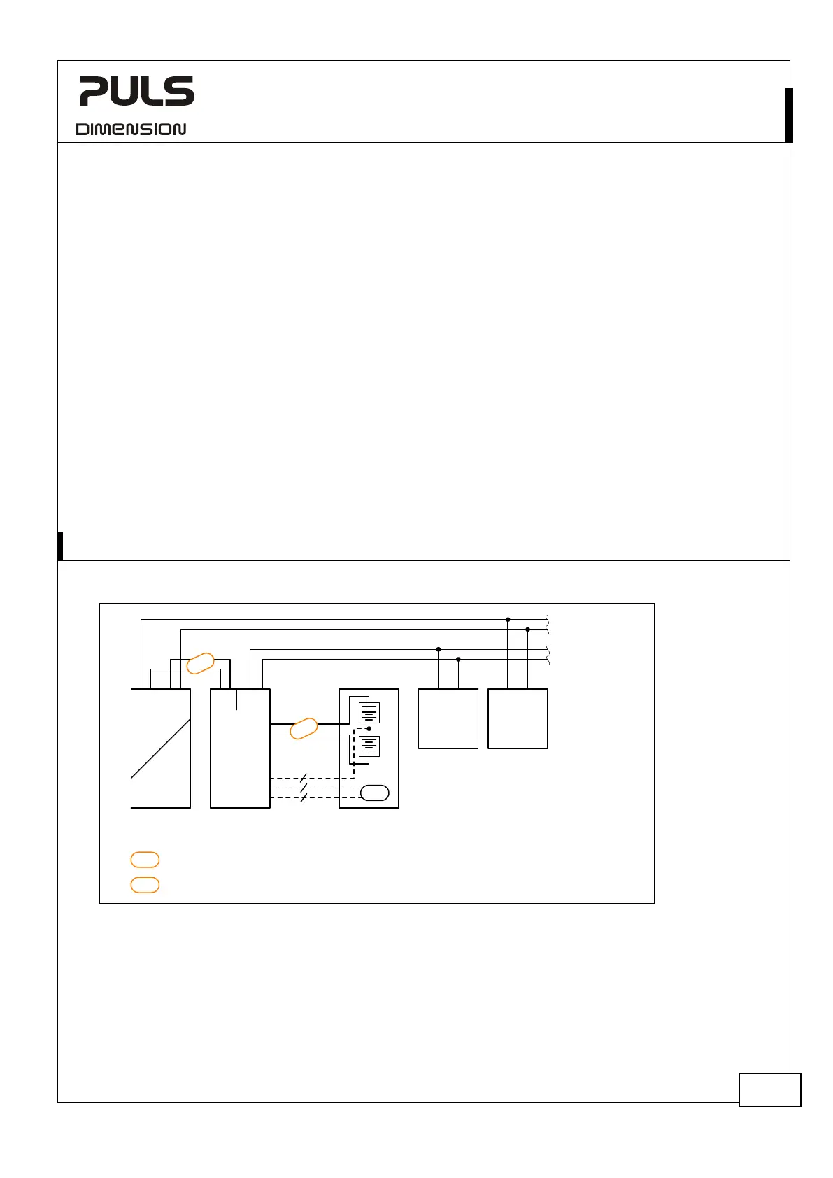
Use a 4A fuse (ATOF® 287 004 from Little fuse or an UL listed fuse with same characteristics) between the connection point of the two
12V batteries and the “Center Tap” connection point of the DC-UPS. An equivalent protection is included on the original battery
modules. The center tap connection is not mandatory but enables an individual charging and monitoring of the two batteries.
Optionally, a PT1000 temperature sensor can be connected to terminals point 11 and 12 to measure the battery temperature. This
adjusts the charging voltage according to the battery temperature which extends the battery life. This sensor is already installed in the
original battery modules.
24V Power
Supply
+
-
UB40.241
Input
+
-
+
-
24V Battery
Module
+
Buffered
Load
+
-
Non-
buffered
Load
+
-
24V
buffered
branches
24V
Non-bufferd
branches
Temp.
Sensor
Output
Battery
-
Bat1
12V
Bat2
12V
Center Tap
Temp. Sensor
DC-UPS
AC
DC
Output
Input
N L PE
+
+
optional
UZK24
+
-
Note1
Note2
Do not use wires smaller than 6mm
2
(AWG 10) and not longer than 2x1m
between the power supply and the DC-UPS controller.
Do not use wires smaller than 6mm
2
(AWG 10) and not longer than 2x1.5m
between the battery and the DC-UPS controller.
Note1
Note2
 Loading...