Terminal Connections
2 Wire
Terminal 1 + ve: Direct Current (DC) input (11-30VDC)
Terminal 2 - ve: Current Output (4-20mA)
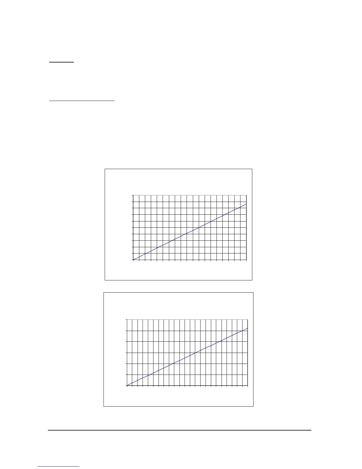
Loop Resistance
For two wire operation the maximum cable resistance allowable can be calculated
from the graph below. For example if an IMP+
IMP+IMP+
IMP+ were supplied from 24v connected
as a 2 wire unit (4-20mA only), the maximum total cable resistance is 590 ohms,
for a typical 77 ohm /km cable this would mean a maximum cable length of
590/77 = 7.6km, remember this total cable resistance, so this figure has to be
divided by 2 to give 3.8km max distance.
Allowable total cable resistance for Loop-
powered IMP
0
100
200
300
400
500
600
700
800
900
1000
11 12 13 14 15 16 17 18 19 20 21 22 23 24 25 26 27 28 29 30
Supply Voltage
Total Cable resistance
Maximum cable resistance vs supply voltage for 2 wire mode.
@ 22mA output
0
200
400
600
800
1000
1200
7 8 9 10 11 12 13 14 15 16 17 18 19 20 21 22 23 24 25 26 27 28 29 30
4-20mA supply Voltage
Maximum load resistance
Maximum cable resistance vs supply voltage for 3 wire mode.

 Loading...