TMS STRING PINSPOTTER OWNER’S MANUAL
400-051-010-01 Rev. Date: 7/17 Page 1-19
Graphics
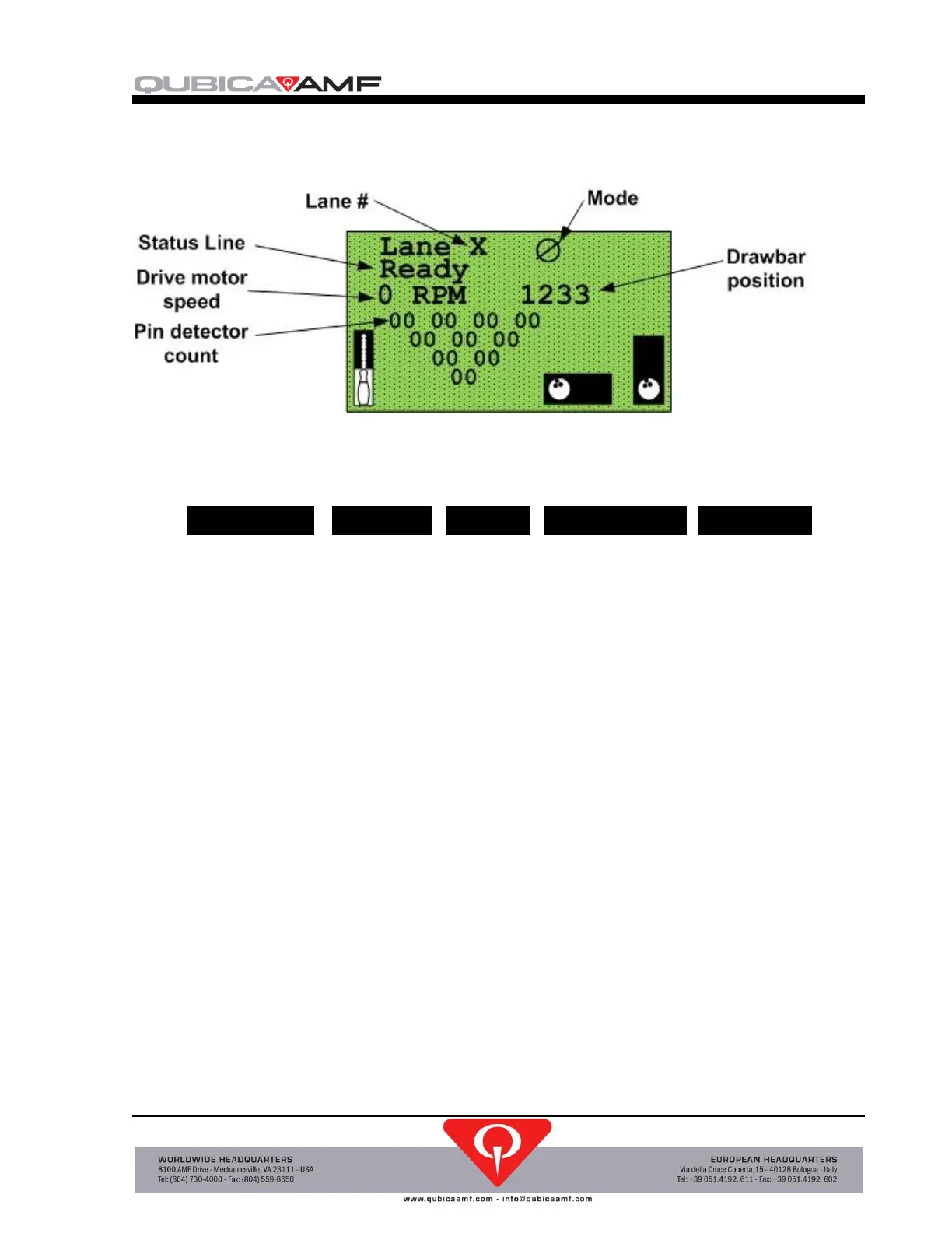
The graphics menu displays a graphic indication of the pinspotter status as shown below:
The Status Line indicates the state of the pinspotter, such as: Ready, Spotting Pins, Parking,
Adjusting Pins, and Detangling. It can also indicate any of the following error messages:
Error messages are shown in reverse text.
Pin Detector Data is usually 00 or 01, unless the pins are moving. After the pins are set on the
pin deck and are no longer moving, the control chassis resets the pin data to 00 so that it can
sense additional pin movement. This graphic indication can be used to verify pin detector
operation during troubleshooting.
Drawbar position gives an indication of the position of the drawbar as determined by the motor
encoder count. A count over 1,200 indicates the drawbar is near the front limit of its travel. A
zero count signifies that the drawbar is at the home position towards the rear of the pinspotter.
Output Control
Within the output control menu you can control every output by using right and left arrow
buttons once the desired output is highlighted. Below is a list of the outputs that can be
controlled:
Ball Lift, Mask Ball 1, Mask Ball 2, Bumper, Buzzer, Spare Relay, Foul Light, Foul Buzzer,
Backend Pad, Backend Motor, Red Stack Light, Green Stack Light, Pit Light 1, Pit Light 2,
Brake, Red Lamp, Counter, and Drawbar Motor.
 Loading...