TMS STRING PINSPOTTER OWNER’S MANUAL
400-051-010-01 Rev. Date: 7/17 Page 3-9
Using Diagnostics and the Pin Detector Circuit Board as Troubleshooting Aids
(Refer to the TMS Chassis Logic Tree for a road map of chassis menu items.)
The control chassis diagnostics menu can be used to check the operating status of many of
the pinspotter’s components. For instance, the operation of the ball detector can be checked
from either the Text or Graphics diagnostics windows. Using the Text menu, the possible
indications are Ball or No Ball. This is an active indication, so by passing an object through
the ball detector’s beam, the indication should go from No Ball to Ball and back to No Ball.
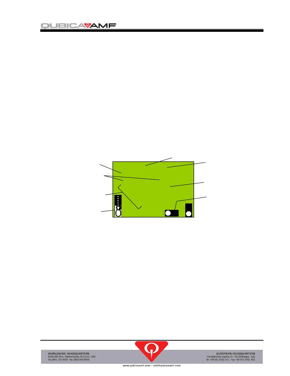
The diagnostics Graphics screen (see Figure 3-1) displays a combination of icons and
numerals in a layout that allows you to see many of the machine’s parameters at one time.
These diagnostic tools provide more information than can be seen by observing just the
component. For example, there is an LED on the ball detector that lights when the beam is
broken telling you that the detector has sensed the object, but the diagnostics menus tell you
that this information has been received by the chassis, and that the cable and connections, as
well as the applicable part of the chassis circuitry, are also functioning correctly. Data can be
delayed slightly when viewing the graphics screen.
Figure 3-1, Diagnostics Graphics Screen
The Pin Detector Circuit Board Assembly (Figure 3-2) provides indications for the pin
encoders, the brake solenoids, and circuit board communications in the form of LEDs. Ten
numbered LEDs form a line across the enclosure cover. These LEDs blink on and off in
response to string movement to indicate that the pin encoders are functioning. These LEDs
also light to show which pin brake solenoids are being energized. Since the brake solenoids
are energized only briefly, the LEDs are lit only briefly and then return to their pin sensing
function. Another LED labelled Main Brake, located just to the left of the numbered LEDs,
serves to act in a permissive function for the brake solenoids and will also light when the
solenoids are energized. Three additional LEDs can be seen by looking downward through the
gap in the cutout for the left hand group of string sensor (pin encoder) connectors. One of
these is the “heartbeat” of the board and flashes to indicate the board internal circuits are
functioning. The remaining two LEDs flash to indicate that transmit and receive
communications to and from the control chassis are functioning.
NOTE: Removing the Pin Detector Circuit Board Cover will void its warranty.
 Loading...