TMS STRING PINSPOTTER OWNER’S MANUAL
400-051-010-01 Rev. Date: 7/17 Page 1-11
A power supply line is run from the main service distribution panel circuit breaker to
each pair of pinspotters. A three conductor drop cord terminating with the provided
power connector, is plugged into the control chassis to supply the necessary electrical
power. Each pair of pinspotters share a control chassis which can be used with or without
an automatic scoring system.
The control chassis is mounted to a bracket on the upper table between the two
pinspotters and is used to supply the necessary electrical power to all components on a
pair of pinspotters. A combination ON-OFF switch/circuit breaker for each lane is
located on the top of the control chassis, as is a logic control power switch and a power
switch that controls power to the ball accelerator (sometimes referred to as the back end).
Warning High voltage is present in the pinspotter control chassis and on the pin
detector circuit board. The main circuit breakers must always be OPEN or
the power plug DISCONNECTED before working on any electrical
component or cable.
The Control Chassis contains a keypad and display through which you can check and set
all of the machine’s operating parameters. A diagnostics button is provided to allow you
to check the status of the various machine components and circuit breakers and a number
to error messages can be displayed as well to help in the troubleshooting of any problems
that should arise.
The Display
Figure 3, The Main Screen
Figure 3 shows a representation of the control chassis’ liquid crystal display. Each pair
of horizontal lines represents a lane with the pins at the right. (Horizontal lines that look
like train tracks indicate the controller is calling for the bumpers, if installed, to be up.)
The lanes shown here are numbered 1 & 2, but they will show the lane numbers entered
into your chassis during the initial setup. For two-lane installations, they will be lanes 1
& 2. For larger installations, they will be numbered sequentially. This is especially
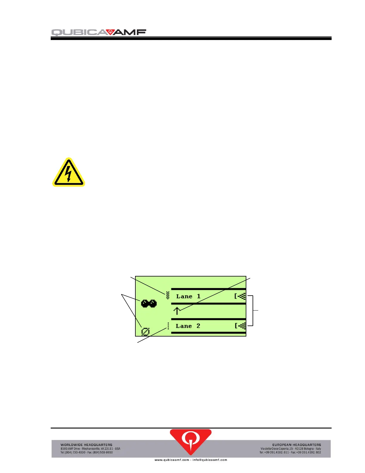 Loading...