Section IV - QCS900 & QCS1600
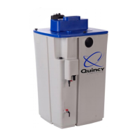
Installation Site
A sealed floor or spill basin is required.
It is crucial to ensure that untreated
condensate or oil cannot get into the
sewer system in the event of damage.
The floor area must be stable and level
(maximum inclination 1°) to ensure reliable
functioning of the QCS.
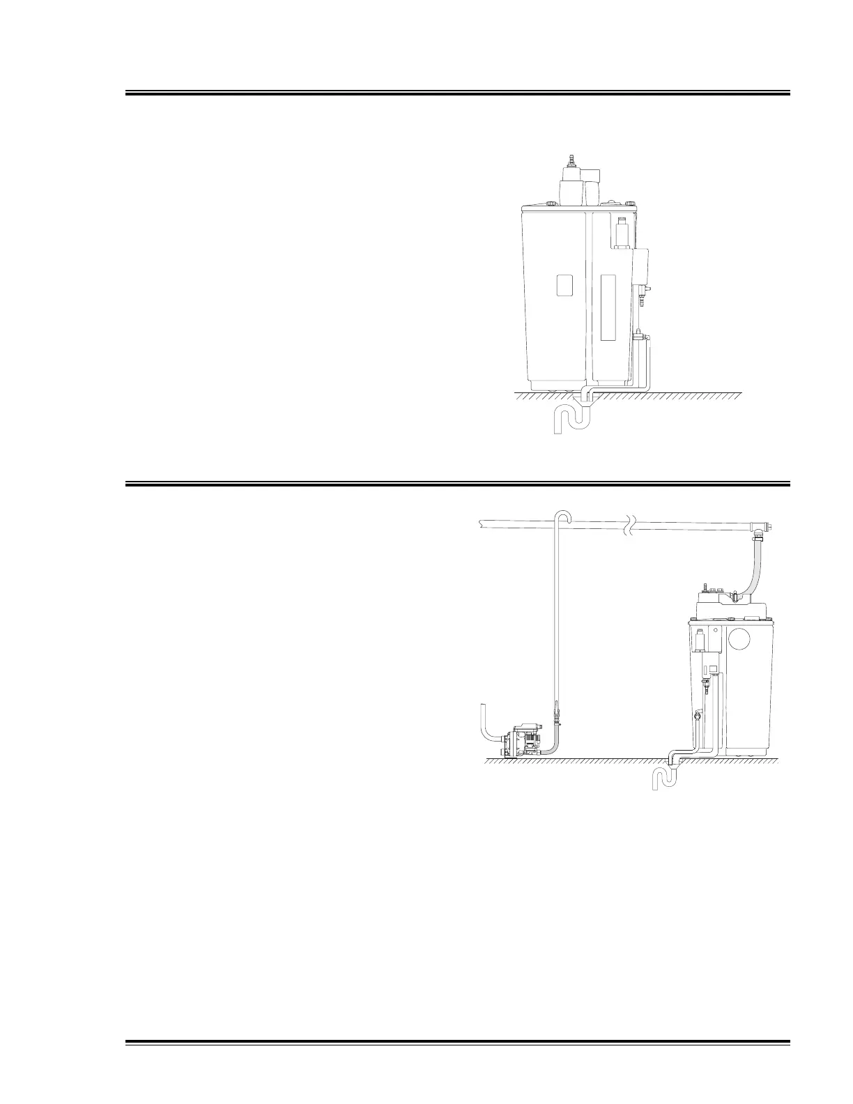
Oil Collector Connection
Place the collector on the same floor level
as the QCS separator to ensure proper
discharge.
Firmly screw the outlet pipe to the
collector so that the discharge cannot leak
out (in the event of overloading).
Inflow
Up to 4 feed points can be connected
directly to the QCS900 and QCS1600 oil
water separator.
If there are more than 4 feed points, it will
be necessary to lay a collecting line.
Ring system along the wall:
nominal diameter 1" (DN 25)
above QCS inlet (height above floor)
slight slope down to the QCS unit (min.
1°)
Feed in the condensate from the top into
collecting line (swan-neck pipe bend).
♦
♦
♦
Quincy Compressor-QCS High Efficiency Emulsion Separators 19
 Loading...