Preparing the Analyzer for Use
R&S
®
ZVA
12Getting Started 1145.1090.62 ─ 13
priate physical unit. x1 is equivalent to OK ENTER. It confirms the previous entry
and deactivates the input field (closes the numeric entry bar).
●
In character input fields, the G/n, M/μ, k/m keys enter the letters G, M, K, respec-
tively. x1 is equivalent to OK ENTER. It confirms the previous entry and deacti-
vates the input field.
The ESC CANCEL and OK ENTER keys are equivalent to the corresponding keys in
the NAVIGATION keypad.
BACK deletes the last character before the cursor position or the selected character
sequence. If an entire numeric value is selected, BACK moves the cursor in front of the
first digit.
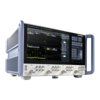
1.1.5 Rotary Knob
The rotary knob increases and decreases numerical values, scrolls within lists, acti-
vates controls and confirms entries. Turning or pressing the rotary knob is equivalent to
the action of the ↑ and ↓ keys or the OK ENTER key in the NAVIGATION keypad.
STEP SIZE opens an input box to select the steps (in units of the current physical
parameter) between two consecutive values if the rotary knob is turned to increase or
decrease numeric values. See chapter 3.2.3.3, "Step Size", on page 65.
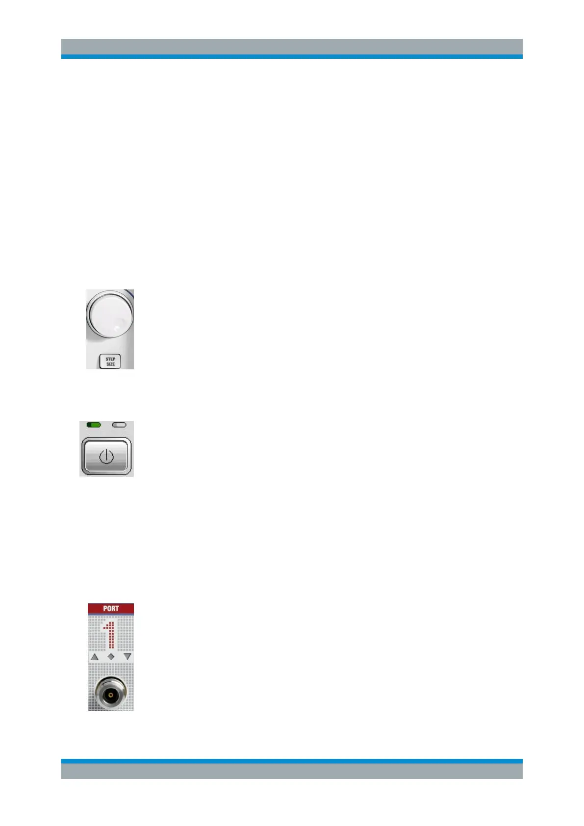
1.1.6 Standby Key
The standby toggle switch is located in the bottom left corner of the front panel.
The key serves two main purposes:
●
Toggle between standby and ready state.
●
Shut down the instrument.
1.1.7 Front Panel Connectors
The test ports and various additional connectors are located on the front panel of the
analyzer.
1.1.7.1 Test Ports
N-connectors (or smaller ruggedized connectors for microwave analyzer types), num-
bered 1, 2 ... The test ports serve as outputs for the RF stimulus signal and as inputs
for the measured RF signals from the DUT (response signals).
●
With a single test port, it is possible to generate a stimulus signal and measure the
response signal in reflection.
●
With 2, 3 or 4 test ports, it is possible to perform full two-port, 3-port or 4-port mea-
surements; see chapter 3.3.1, "S-Parameters", on page 76. Note that for most
R&S ZVA models, ports 2k-1 and 2k share a common generator; only for
R&S ZVA24 with 4 ports and 4 generators (order no. 1145.1110.28), R&S ZVA40
Front Panel Tour

 Loading...