System Overview
R&S
®
ZVA
76Getting Started 1145.1090.62 ─ 13
The definitions in this and the following sections apply to general n-port DUTs. An ana-
lyzer with a smaller number of test ports provides a subset of the n-port quantities.
3.3.1 S-Parameters
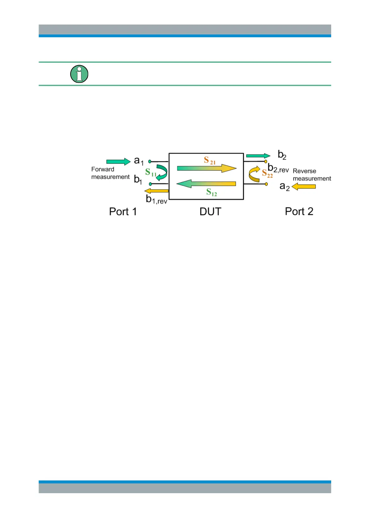
S-parameters are the basic measured quantities of a network analyzer. They describe
how the DUT modifies a signal that is transmitted or reflected in forward or reverse
direction. For a 2-port measurement the signal flow is as follows.
The figure above is sufficient for the definition of S-parameters but does not necessa-
rily show the complete signal flow. In fact, if the source and load ports are not ideally
matched, part of the transmitted waves are reflected off the receiver ports so that an
additional a
2
contribution occurs in forward measurements, an a1 contribution occurs in
reverse measurements. The 7-term calibration types Txx take these additional contri-
butions into account.
The scattering matrix links the incident waves a
1
, a
2
to the outgoing waves b
1
, b
2
according to the following linear equation:
2
1
2221
1211
2
1
a
a
SS
SS
b
b
Meaning of 2-port S-parameters
The four 2-port S-parameters can be interpreted as follows:
●
S
11
is the input reflection coefficient, defined as the ratio of the wave quantities
b
1
/a
1
, measured at PORT 1 (forward measurement with matched output and a
2
=
0).
●
S
21
is the forward transmission coefficient, defined as the ratio of the wave quanti-
ties b
2
/a
1
(forward measurement with matched output and a
2
= 0).
●
S
12
is the reverse transmission coefficient, defined as the ratio of the wave quanti-
ties b
1
(reverse measurement with matched input, b
1,rev
in the figure above and a
1
=
0) to a
2
.
●
S
22
is the output reflection coefficient, defined as the ratio of the wave quantities b
2
(reverse measurement with matched input, b
2,rev
in the figure above and a
1
= 0) to
a
2
, measured at PORT 2.
Measured Quantities

 Loading...