Preparing the Analyzer for Use
R&S
®
ZVA
21Getting Started 1145.1090.62 ─ 13
1.3.6 Connecting the Analyzer to the AC Supply
The network analyzer is automatically adapted to the AC supply voltage supplied. The
supply voltage must be in the range 100 V to 240 V; 50 Hz to 60 Hz. The mains con-
nector is located at the bottom left corner of the rear panel.
► Connect the network analyzer to the AC power source using the AC power cable
delivered with the instrument.
The maximum power consumption of the analyzer is 450 W. The typical power con-
sumption is listed in the "Specifications".
The network analyzer is protected by two fuses as specified on the label on the power
supply. The fuses are located on an AC Fuse Board (order no. 1145.3906.02) which
must be replaced to change the fuses. Replacing the AC Fuse Board requires opening
the instrument and is described in the service manual.
1.3.7 Power on and off
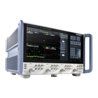
The mains connector is located at the bottom left corner of the rear panel.
► To turn the power on or off, press the AC power switch to position I (On) or 0 (Off).
After power-on, the analyzer is in standby or ready state, (see chapter 1.3.8, "Standby
and Ready State", on page 21) depending on the state of the STANDBY toggle
switch at the front panel when the instrument was switched off for the last time.
The AC power switch can be permanently on. Switching off is required only if the
instrument must be completely removed from the AC power supply.
1.3.8 Standby and Ready State
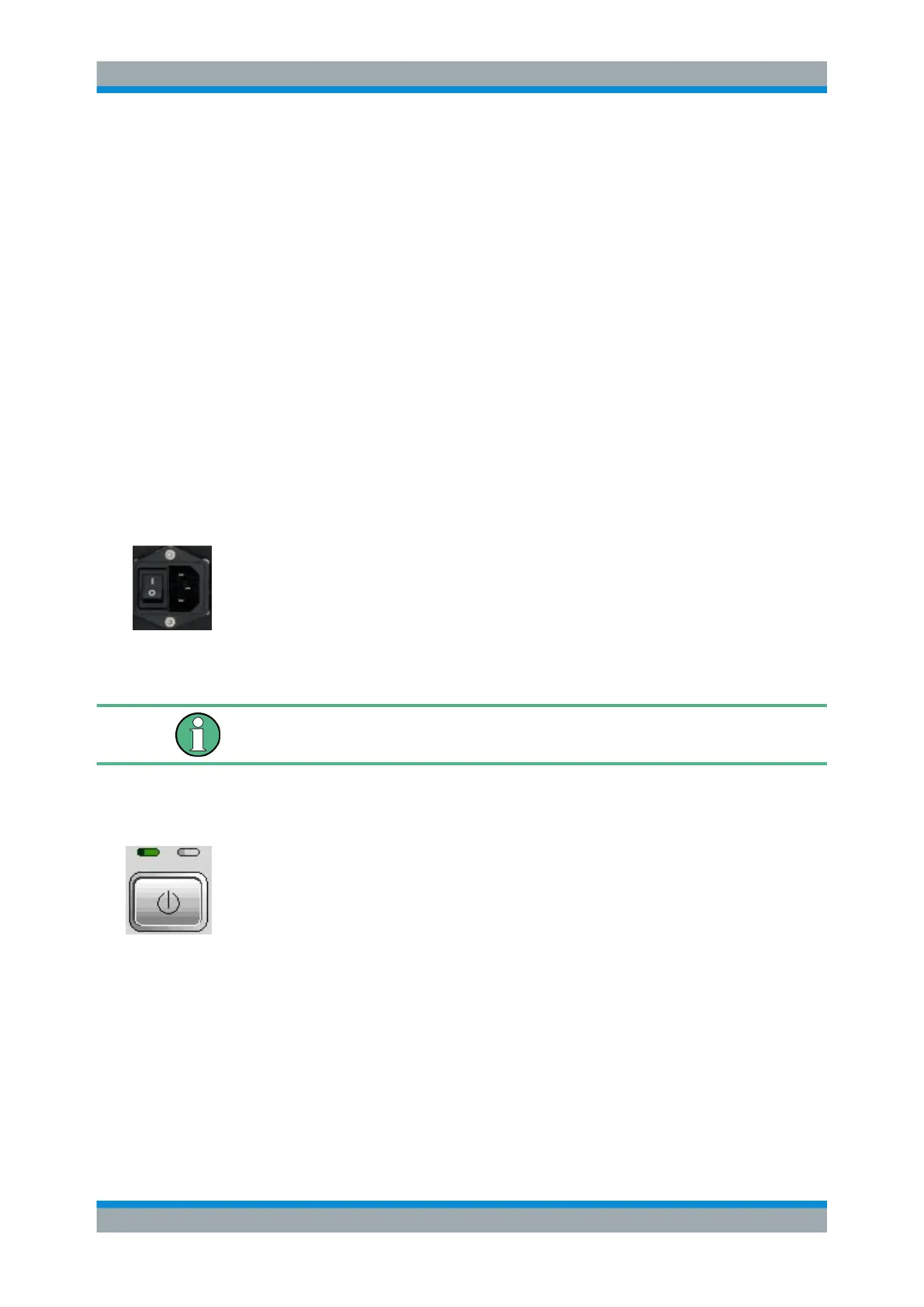
The STANDBY toggle switch is located in the bottom left corner of the front panel.
► After switching on the AC power (see chapter 1.3.7, "Power on and off",
on page 21) press the STANDBY key briefly to switch the analyzer from the
standby to ready state or vice versa.
●
In standby state, the right, amber LED is on. The standby power only supplies the
power switch circuits and the optional oven quartz (OCXO, 10 MHz reference oscil-
lator, option R&S ZVAB-B4, order no. 1164.1757.02). In this state it is safe to
switch off the AC power and disconnect the instrument from the power supply.
●
In ready state, the left, green LED is on. The analyzer is ready for operation. All
modules are power-supplied and the analyzer initiates its startup procedure.
Putting the Analyzer into Operation

 Loading...