22 DSM25 Owner’s Handbook
• Secure cables in place using tie-wraps or lacing twine. Coil any extra cable
and tie it out of the way.
CAUTION: Do Not Cut or Splice the Transducer Cable
• There is high voltage on the transducer cable. Splicing could
create a safety hazard.
• Cutting the transducer cable severely reduces sonar
performance. If the cable is cut, it must be replaced—it cannot
be repaired.
• Cutting the transducer cable will void the warranty and
invalidate the European CE mark.
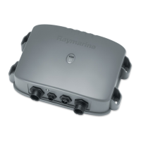
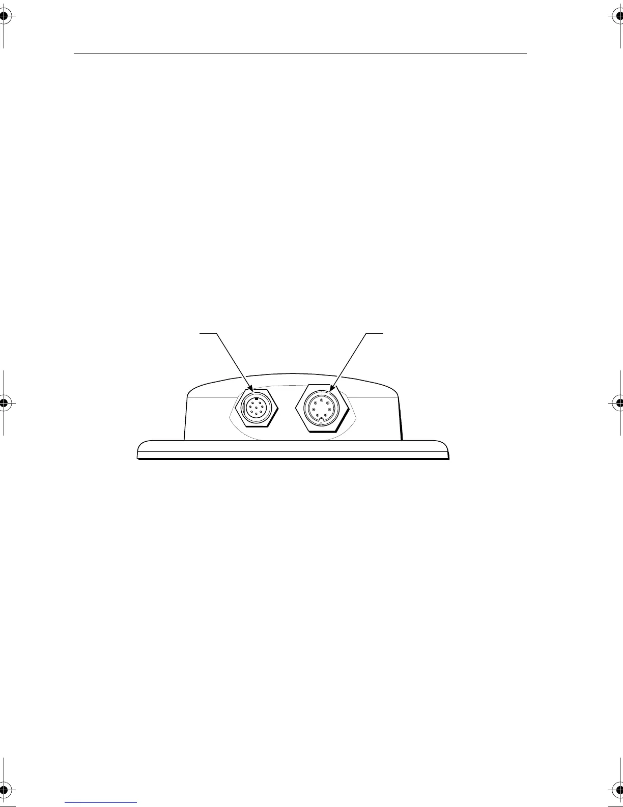
2.7 System Connections
The connector panel provides the following connection sockets:
Display Connection
The 8-pin connector labelled DISPLAY provides a connection for both power and
data to the A65 display.
There is no power switch on the DSM25. The unit turns on when the network
cable is attached to an A65 display and the A65 is energized.
Transducer Connection
A 30 ft (10m) cable is supplied with the transducer.
to A65
to transducer
D7743-1
81254.book Page 22 Monday, March 6, 2006 2:29 PM
 Loading...