6 SmartPilot Series Commissioning Guide
3. Select the appropriate circuit breaker or fuse:
4. Route the cables back to the SmartPilot computer.
5. Connect the cables to the POWER inputs.
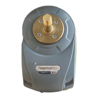
Drive unit S1 S2 &
S3
Fuse Thermal over-current
circuit breaker
Rotary, linear, hydraulic pump,
hydraulic linear
Type 1: 12 V
Type 1: 24 V
Type 2: 12 V
Type 2: 24 V
Type 3: 12 V and 24 V
¸¸
¸
¸
¸
¸
25 A
25 A
40 A
30 A
40 A
20 A
20 A
30 A
30 A
30 A
I/O drive ¸ ¸ 15 A 10 A
CR pump solenoids
Volvo Penta IPS system (S3G)
¸ 10 A 10 A
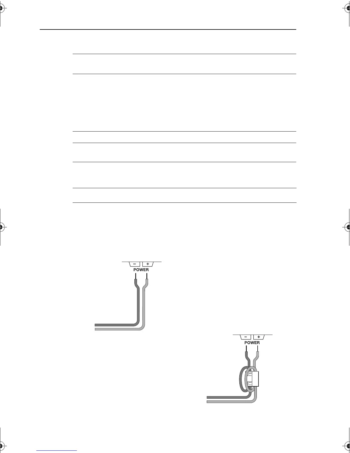
S1 Systems S2 & S3 Systems
• Strip 8–10 mm (½ in) of insulation from
the end of each cable.
• Use a small screwdriver to loosen the
screw on the terminal block.
• Insert the stripped cable into the terminal
and tighten the screw.
• Strip 8–10 mm (½ in) of insulation from
the end of each cable.
•For the POWER connection:
Attach the suppression ferrite (supplied)
around both the positive and negative
power cables, between the cable clamp
and SmartPilot computer.
When you attach the ferrite, you must
loop both power cables so that the ferrite
encloses two passes of each cable.
Secure the ferrite with the small tie-wrap.
• Use a small screwdriver to loosen the
screw on the terminal block.
• Insert the stripped cable into the terminal
and tighten the screw.
D6390-2
Ferrite
D6391-2
81273_1.book Page 6 Thursday, November 10, 2005 8:25 AM

 Loading...