RMI-Q installation guide
3.2
System
installation
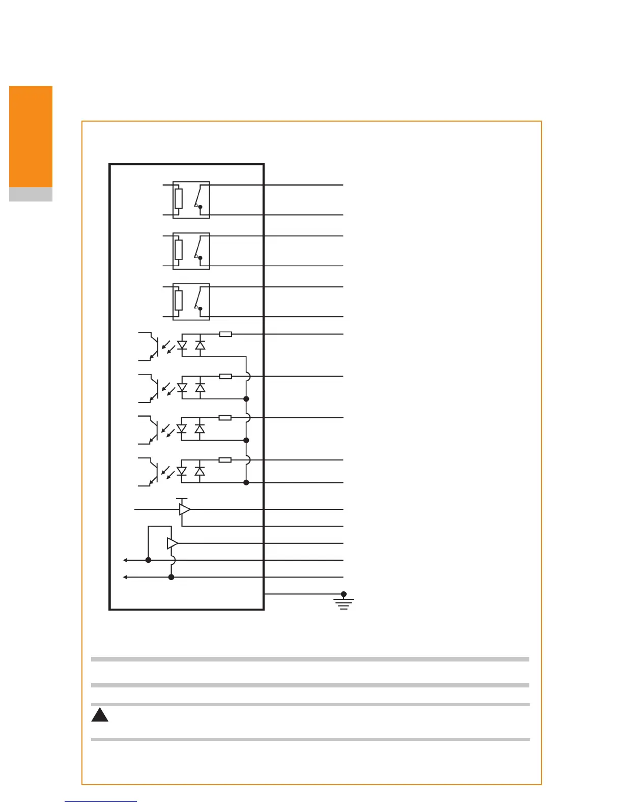
Wiring diagram (with output groupings shown)
12 V to 30 V
Turquoise
Violet
Green
Turquoise/black
Violet/black
Green/black
White
Pink
White/red
Brown
Yellow
Signal
Return
See NOTE
Orange
Red
Black
Green
Grey
White/blue
RMI-Q
Machine ground (star point)
Power supply (12 V to 30 V)
Error (SSR)
Probe status 1 (SSR)
Low battery (SSR)
Machine start input [P1]
Machine start input [P2]
Machine start input [P3]
Machine start input [P4]
Machine start common
Probe status 2b
!
CAUTION: The power supply 0 V should be terminated at the machine ground (star point).
A negative supply can be used when wired appropriately.
Driver
Screen
Driver
Probe status 2a
(5 V isolated driven skip)
5 V
0 V
NOTE: A switch can be added on installation to aid with powering up the RMI-Q when partnering.
}
}
}
}
}

 Loading...