108
The order in which these messages will
be displayed will depend on which com-
ponents are energized first. The order
listed here assumes that the furnace
and condenser are energized at the
same time. If not, the order of display
will be in the order that the components
are turned on.
When the system has found all neces-
sary components, the text area of the
communicating thermostat will go
blank. This is an
indicator that the sys-
tem is operating properly. Proceed by
engaging a typical thermostat call to
determine if operation is correct as
described in the section of this book
titled START UP PROCEDURES” to
test heating, cooling and fan operation
and to make necessary adjustments.
ACTIVE FAULT CODES
WITH COMMUNICATING
SYSTEMS
Two levels of fault codes exist: (1) Non-
critical and (2) Critical. In general a
n
on-critical fault permits all (or nearly
all) operations to proceed and a critical
fault prevents all (or nearly all) opera-
tions from proceeding. Detailed expla-
nations are given for each fault code
and how to diagnose and troubleshoot
problems by fault code displayed in the
“TROUBLSHOOTING” section of this
manual.
Active faults of either level will be dis-
played at the thermostat in the
“ACTIVE FAULT
” a
rea of the thermo-
stat. To enter the furnace “ACTIVE
FAULT” area using a communicating
thermostat, see the installation and
operation instructions for that thermo-
stat.
For detailed user menu text, navigation
and descriptions, refer to the section of
this manual titled COMMUNICATING
SYSTEMS under the subsection titled
USER MENUS.
Below describes some basic methods
for entering and viewing furnace fault
messages an
d user menus for two dif-
ferent communicating thermostats avail-
able at the time of publication of this
manual. Further setup and installation
information on these thermostats can
be found in their respective installation
and operation instructions.
FIGURE 65
WIRING DIAGRAM
–
COMMUNICATING CONFIGURATION
ST-A1118-01-3
(-)HC-TST501CMMS PRO-
GRAMMABLE COMMUNI-
CATING THERMOSTAT
TIPS FOR NAVIGATING FURNACE
USER MENUS USING THE (-)HC-
TST501CMMS THERMOSTAT
NOTE: The (-)HC-TST501CMMS ther-
mostat does not have built-in humidifi-
cation control in heating mode (or any
other mode). However, dehumidification
is possible in cooling. If humidification
control is required, a separate humidis-
tat or a communicating thermostat w
ith
humidification capability (such as
(-)HC-TST550CMMS) must be used.
(See the section of this manual titled
Accessories, Humidification and
Dehumidification for wiring of a sep-
arate humidistat.)
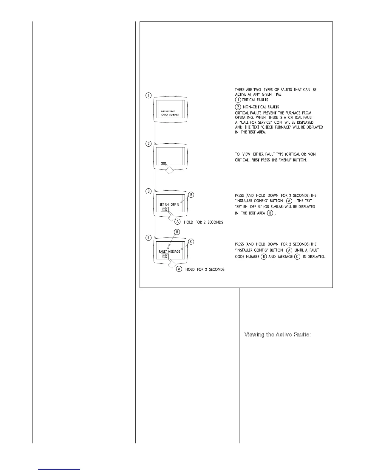
V
iewing the Active Faults:
Figure
65 demonstrates how to view the
furnace active faults with the (-)HC-
TST501CMMS communicating ther-
mostat.
VIEWING DETAILED FAULT MESSAGES
ON THE (-)HC-TST501CMMS
COMMUNICATING THERMOSTAT
 Loading...


