30
GAS SUPPLY AND PIPING
GAS SUPPLY
THIS FURNACE IS EQUIPPED
AT THE FACTORY FOR USE ON
NATURAL GAS ONLY. CONVER-
SION TO LP GAS REQUIRES A
SPECIAL KIT
A
VAILABLE FROM
THE DISTRIBUTOR
. FAILURE TO
USE THE PROPER CONVER-
SION KIT CAN CAUSE FIRE,
CARBON MONOXIDE POISON-
ING, EXPLOSION, PROPERTY
DAMAGE, PERSONAL INJURY
OR DEATH.
See the conversion kit index sup-
plied with the furnace. This index
identifies the proper LP Gas
Conversion Kit required for each
particular furnace.
IMPORTANT: Any additions, changes
or conversions required for the furnace
to satisfactorily meet the application
should
be made by a qualified installer,
service agency or the gas supplier,
using factory-specified or approved
parts.
IMPORTANT: Connect this furnace
only to gas supplied by a commercial
utility.
IMPORTANT: A U.L. recognized
fuel gas and CO detector(s) are rec-
ommended in all applications, and their
installation should be in accordance
with the manufacturer’s recommenda-
tions and/or local laws, rules, regula-
t
ions or customs.
GAS PIPING
Install the gas piping according to all
local codes and regulations of the utili-
ty company.
If possible, run a separate gas supply
line directly from the meter to the fur-
nace. Consult the local gas company
for the location of the manual main
shut-off valve. The gas line and man-
ual gas valve must be adequate in
size to prevent undue pressure drop
and never smaller than the pi
pe size
!
WARNING
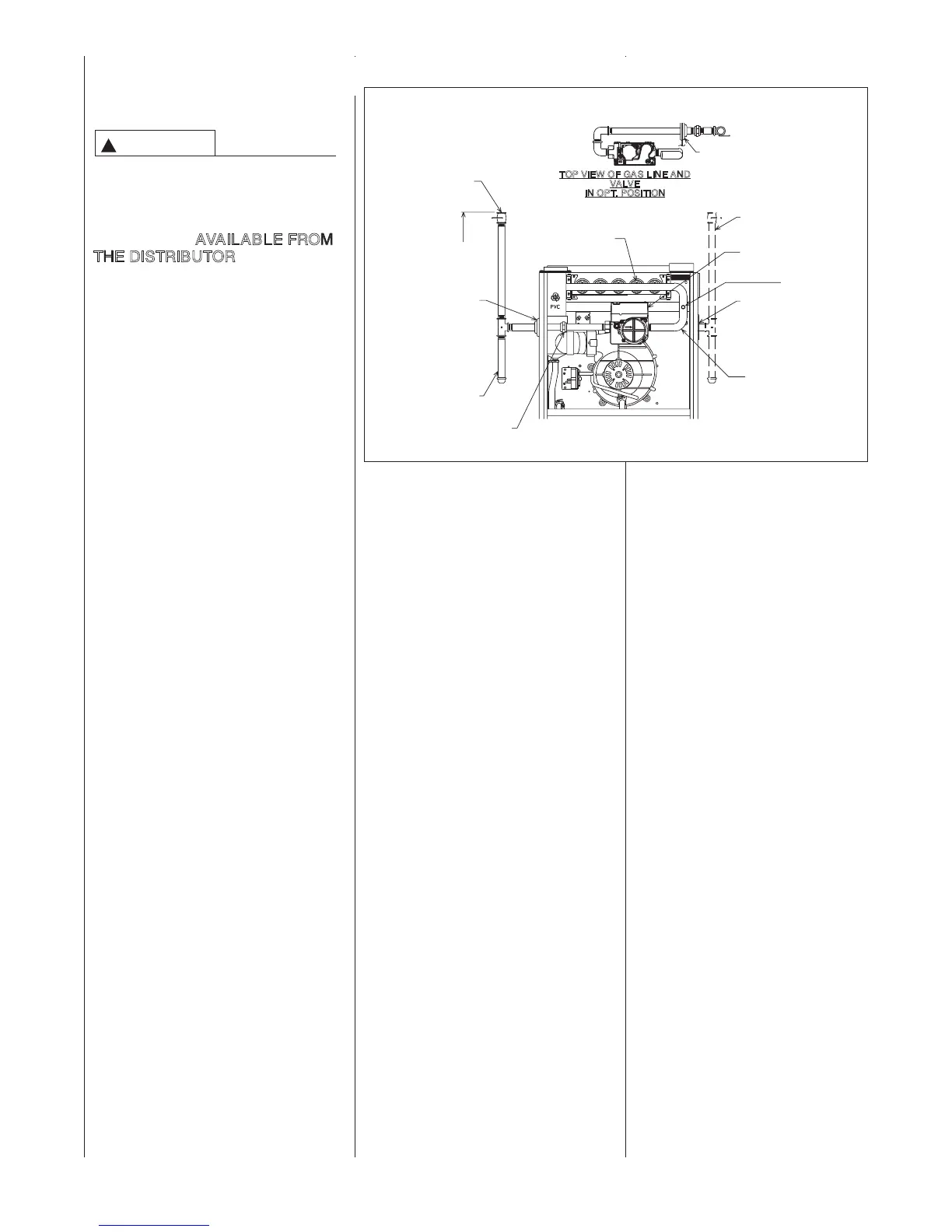
FIGURE 23
GAS PIPING -- UPFLOW INSTALLATION
(GAS VALVE MAY BE DIFFERENT
THAN SHOWN)
A1122-01_1
TOP VIEW OF GAS LINE AND
VALVE
IN OPT. POSITION
OPTIONAL GAS LINE
POSITION
PLUG
(IN NORMAL
POSITION)
MANIFOLD
PRESSURE TAP
MANIFOLD
GROMMET
GAS VALVE
DRIP LEG
4 TO 5 FT.
ABOVE FLOOR
REQ’D BY
SOME
UTILITIES.
NOTE:
WHEN GAS LINE IS IN OPT.
POSITION, SWAP LOCATION
OF GROMMET AND PLUG.
MANUAL
GAS VALVE
BURNERS
UNION
(TYPICAL INSTALLATION)
GROMMET
(IN NORMAL
POSITION)
IMPORTANT: Do not run a flexible gas connector inside the unit.
 Loading...


