43
LP GAS AT HIGH ALTITUDE
ELEVATIONS IN THE U.S.
LP Gas is a manufactured gas that has
consistent heating value across most
regions.
The National Fuel Gas Code (N.F.G.C.)
guidelines are used with the following
exception:
The recommended LP Gas high altitude
orifice selections differ slightly in that
the NFGC LP orifice chart, as they are
not accurate for the RGFG gas fur-
naces. The National Fuel Gas Code LP
or
ifices a
re based on an 11” of water
column pressure at the orifice, which
differs from products that use 10” of
water column at the orifice. This differ-
ence requires a deviation from the
NFGC orifice size recommendations.
The Sea Level input should still be
reduced by 4% per thousand ft. and the
orifice size must be selected based on
the reduced input selection shown in
Table 13.
Orifice Ordering Informati
on
O
rifice sizes are selected by adding the
2-digit drill size required in the orifice
part number. Drill sizes available are 39
through 64; metric sizes available
1.10mm (-90) and 1.15mm (-91):
Orifice Part Number 62-22175-(drill
size)
Example 1:
#60 drill size orifice required
Part #62-22175-60
Example 2:
1.15mm drill size orifice required
Part #62-22175-91
ALTERNATE METHOD FOR
CANADIAN
HIGH-ALTITUDE
DERATE
In Canada, unless an orifice change is
specifically mandated by local codes,
an alternate method of altitude deration
through a reduction in manifold pres-
sure is acceptable as described in
Table 14.
The information in Table 14 is based on
a heating value of 1000 BTU per cubic
feet of natural gas, and 2500 BTU per
cubic feet of LP gas.
IMPORTANT: Actual input rates must
be measured on-site with manifold
pressure adjustment to ensure that an
actual 10% reduction in input rate is
achieved.
TABLE 13
LP Gas Orifice Drill Size and per burner de-rate by elevation based
on 15,000 btu 90+ burners.
IMPORTANT: For 90+ Furnaces only. Do not use this chart for any
80+ Furnace.
Input (per Orifice
Altitude burner) 15000 Size
0 to 2000 ft. 15000 1.15 mm (factory)
2001ⴕ to 3000ⴕ 13200 1.15 mm
3001ⴕ to 4000ⴕ 12600 1.10 mm
4001ⴕ to 5000ⴕ 12000 #58
5001ⴕ to 6000ⴕ 11400 #59
6001ⴕ to 7000ⴕ 1080 #60
7001ⴕ to 8000ⴕ 10200 #62
8001ⴕ to 9000ⴕ 9600 #63
9001ⴕ to 10000ⴕ 9000 #64
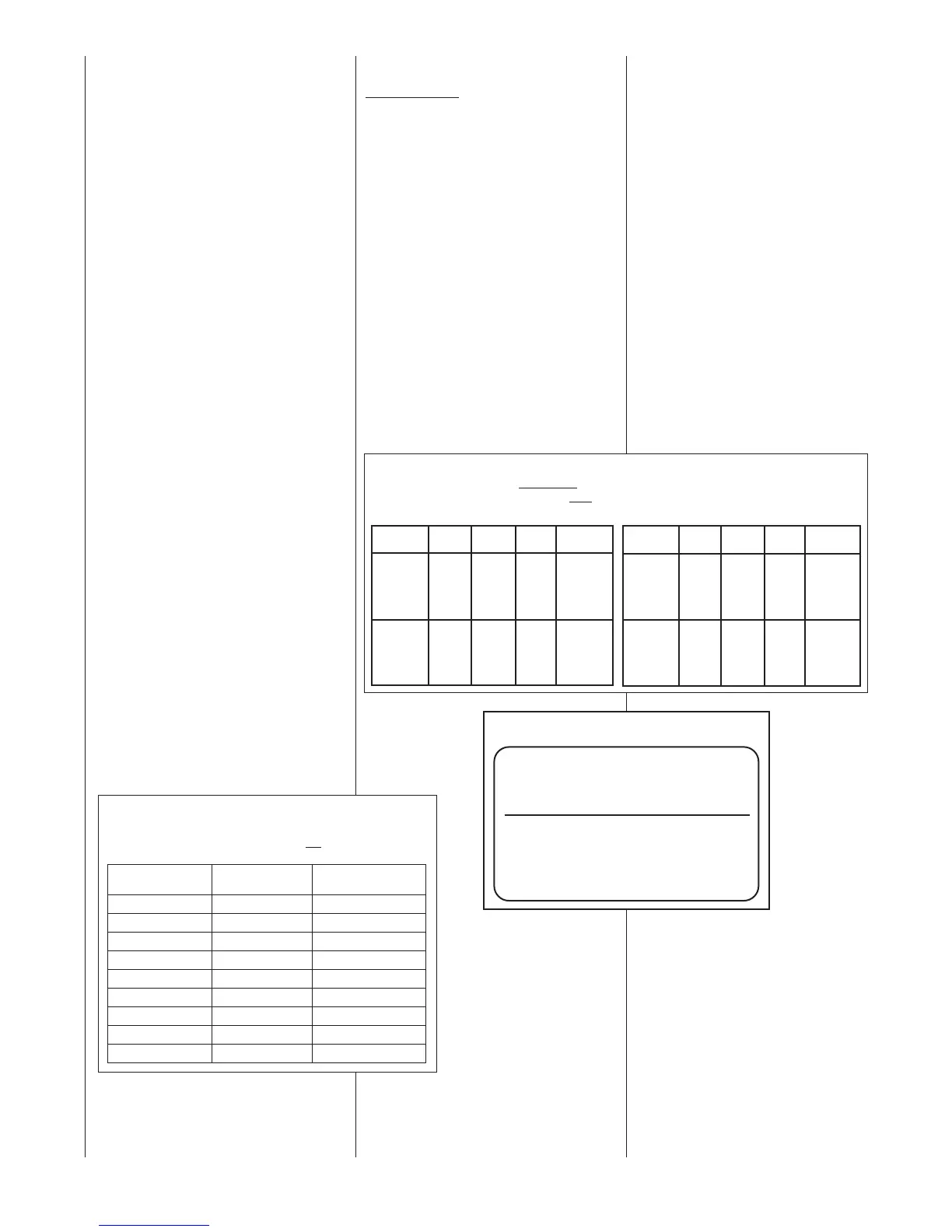
TABLE 14
ALTERNATE METHOD FOR CANADIAN HIGH-ALTITUDE DERATE
IMPORTANT: 90+ MODELS ONLY. DO NOT
USE THIS CHART FOR ANY 80 PLUS MODELS.
NATURAL GAS LP GAS
ALTITUDE
INPUT
OUTPUT
ORIFICE
SIZE
MANIFOLD
PRESSURE
0’ - 2000’
45,000
60,000
75,000
90,000
105,000
120,000
40,500
54,000
67,500
81,000
94,500
108,000
#50
3.5” W.C.
2001’ - 4500’
40,500
54,000
67,500
81,000
94,500
108,000
36,450
48,600
60,750
72,900
85,050
97,200
#51
3.0” W.C.
ALTITUDE
INPUT
OUTPUT
ORIFICE
SIZE
MANIFOLD
PRESSURE
0’ - 2000’
45,000
60,000
75,000
90,000
105,000
120,000
40,500
54,000
67,500
81,000
94,500
108,000
1.15mm
10” W.C.
2001’ - 4500’
40,500
54,000
67,500
81,000
94,500
108,000
36,450
48,600
60,750
72,900
85,050
97,200
1.10mm
7.6” W.C.
FIGURE 35
MANIFOLD PRESSURE-CHANGE LABEL
THE MANIFOLD PRESSURE OF THIS APPLIANCE HAS
BEEN FIELD ADJUSTED TO OBTAIN THE CORRECT
INPUT RATING FOR INSTALLATION AT ALTITUDES
BETWEEN 2,000 FEET AND 4,500 FEET ELEVATION.
LA PRESSION DU DISTRIBUTEUR D’ALIMENTATION
DE CET APPAREIL A ÉTÉ AJUSTÉ SUR LES LIEUX AFIN
D’OBTENIR LA BONNE PUISSANCE D’ENTRÉE POUR
UNE INSTALLATION ENTRE 2000 ET 4500 PIEDS
D’ALTITUDE.
92-24399-01-01
Once this field adjustment has been
made, the label shown in Figure 35
must be affixed in a conspicuous
location on the front of the furnace
cabinet:
NOTE: This label is supplied in the
information packet shipped with each
furnace.
 Loading...


