15
w
W2
G
W
1
B
ODD
C
R
Air Handler
G
Y
C
R
Single-Stage A/C Thermostat
A/C Outdoor Unit
Y
C
Y2
Y
F
ield Installed
Line Voltage
-
WIRING INFORMAT IO N
Factory Standard
-
W/BL
G/BK
Y
W/BK
BL
G/Y
BR
R
Y/BL
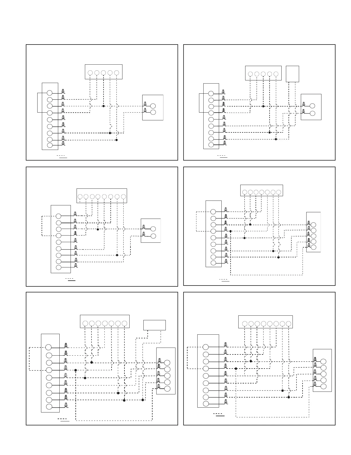
FIGURE 9
TYPICAL THERMOSTAT: STRAIGHT COOLING WITH ELECTRIC
HEAT
FIGURE 10
TYPICAL THERMOSTAT: STRAIGHT COOLING WITH ELECTRIC
HEAT AND USING A HUMIDISTAT FOR DEHUMIDIFICATION
W
2
G
Y
W1
B
ODD
C
R
Air Handler
G
Y
C
R
Single-Stage A/C Thermostat
A
/C Outdoor Unit
Y
C
Humidistat
Y2
Field Installed
Line Voltage
-
WIRING INFORMAT IO N
Factory Standard
-
W
T STR
AND
W/BL
G
/BK
Y
W/BK
BL
G
/Y
B
R
R
Y/BL
FIGURE 11
TYPICAL THERMOSTAT: STRAIGHT COOLING WITH ELECTRIC
HEAT USING A TWO-STAGE FOR DEHUMIDIFYING THERMOSTAT
W
2
G
Y
W1
B
ODD
C
R
Air Handler
C
R
Two-Stage A/C Thermostat
A
/C Outdoor Unit
Y
C
W
G
W2
Y
Y2
Y2
D
F
ield Installed
Line Voltage
-
WIRING INFORMATION
Factory Standard
-
W/BL
G/BK
Y
W
/BK
BL
G/Y
BR
R
Y/BL
*
B
W2
G
Y
W1
B
ODD
C
R
Air Handler
Y
G
W2
E
H
eat Pump Thermostat
Heat Pump
Outdoor Unit
Y
B
C
R
R
D
C
Y
Field Installed
Line Voltage
-
W
IRING INFORMATION
Factory Standard
-
W
/BL
G
/BK
Y
W/BK
G/Y
BR
B
L
R
Y/BL
*
FIGURE 12
TYPICAL THERMOSTAT: HEAT PUMP WITH ELECTRIC HEAT
FIGURE 13
TYPICAL THERMOSTAT: HEAT PUMP WITH ELECTRIC HEAT
AND USING A HUMIDISTAT FOR DEHUMIDIFICATION
B
W2
G
Y
W1
B
ODD
C
R
Air Handler
Y
G
W2
E
Heat Pump Thermostat
Heat Pump
Outdoor Unit
Y
B
Humidistat
C
R
R
D
C
Y2
Field Installed
Line Voltage
-
WIRING INFORMATION
Factory Standard
-
W/BL
G/BK
Y
W/BK
BL
G/Y
BR
R
Y/BL
*
FIGURE 14
TYPICAL THERMOSTAT: HEAT PUMP WITH ELECTRIC HEAT
USING A TWO-STAGE THERMOSTAT FOR DEHUMIDIFICATION
B
W2
G
Y
W1
B
ODD
C
R
Air Handler
Y2
G
W
W2
Two-Stage Heat Pump Thermostat
Heat Pump
Outdoor Unit
Y
B
C
R
R
D
C
Y1
Y2
Field Installed
Line Voltage
-
WIRING INFORMATION
Factory Standard
-
W/BL
G/BK
Y
W/BK
BL
G/Y
BR
R
Y/BL
*
4.4 Typical Thermostat Wiring Diagrams (-)H1V
WIRE COLOR CODE
BK – BLACK G – GREEN PR – PURPLE Y – YELLOW
BR – BROWN GY – GRAY R – RED
BL – BLUE O – ORANGE W – WHITE
*When using 13kW and higher, it is recommitted to jump
W1 and W2 together for maximum temperature rise.
*When using 13kW and higher, it is recommitted to jump W1 and
W2 together for maximum temperature rise.
*When using 13kW and higher, it is recom-
mitted to jump W1 and W2 together for
maximum temperature rise.
*When using 13kW and higher, it is recom-
mitted to jump W1 and W2 together for maxi-
mum temperature rise.
NOTE: These low voltage application diagrams are generic. Your indoor/ outdoor
units may not have all the characteristics shown or may not wire exactly as shown.
Refer to the diagrams and information sent with your indoor/outdoor sections.
 Loading...