36
CONVENTIONAL THERMOSTAT WIRING
6.10 USING THE ON-BOARD LED TO DETERMINE BLOWER CFM (-)H2V
The (-)H2V interface board LED indicates blower output by flashing once for every 100
CFM of airflow. The LED will pause 1/10 second between each flash. (See Table 2.)
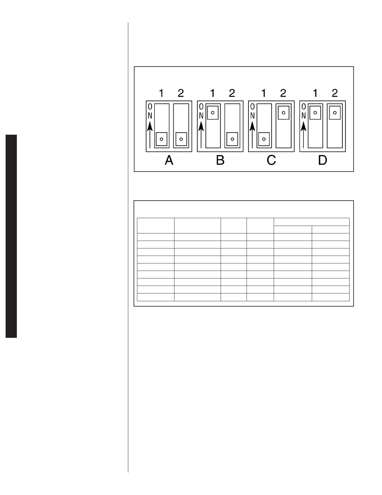
6.11 COOLING AIRFLOW SETTINGS
When not using the Comfort Control
2
System™, the (-)H2V air handler must be config-
ured to deliver the proper airflow. Adjust DIP switches 1 and 2 per these tables for prop-
er unit operation:
*6.12 COOLING AIRFLOW ADJUSTMENTS WITH SINGLE STAGE
CONDENSING UNITS
The (-)H2V series of air handlers can be used with select single-stage condensing units.
Refer to the Engineering Specifications Sheets to determine the required airflow for your
particular combination. Refer to Table 5 to determine the air-flows available for each
(-)H2V air handler. Reference Figures 27-30 for proper wiring of the system.
FIGURE 32
DIP SWITCH SETTING FOR COOLING AIRFLOW (-)H2V
TABLE 11
A
IRFLOW SETTINGS WHEN USING TRADITIONAL 24VAC THERMOSTAT (-)H2V
Airflow (CFM)
2nd Stage (Y2) 1st Stage (Y1)
Switch 2
Position
Switch 1
Position
Outdoor Unit
(also see
Section 5.13)*
(-)H2V
2421HT (-)ASL-025 OFF OFF 775 600
3624HT (-)ASL-037 ON OFF 1175 950
3624HT (-)ASL-039 OFF OFF 1175 825
4824HT (-)ASL-048 OFF OFF 1600 1000
6024HT (-)ASL-060 OFF OFF 1700 1050
2421HT (-)ARL-025 ON OFF 775 600
3624HT (-)ARL-038 ON OFF 1175 950
4824HT (-)ARL-049 ON OFF 1600 1200
6024HT (-)ARL-061 ON OFF 1700 1275
 Loading...