44
9.0 AIR FILTER (Not Factory-Installed)
If a remote filter is installed, it should be sized for a maximum of 300 feet/min. air veloci-
ty for the CFM required.
IMPORTANT: Do not operate system without a filter. A filter is required to protect the
coil, blower and internal parts from excessive dirt and dust.
10.0 SEQUENCE OF OPERATION
10.1 Cooling (cooling only or heat pump)
• When the thermostat “calls for cooling,” the circuit between R, G and Y is completed,
causing the blower to energize. This circuit also closes the contactor (CC) in the out-
door unit starting the compressor (COMP) and outdoor fan motor (OFM).
10.2 Heating (electric heat only)
• When the thermostat “calls for heat,” the circuit between R and W
1
is completed, and
the heater sequencer (HR
1
) is energized. A time delay will follow then: The heating
elements (HE) and the indoor blower motor (IBM) will come on. Units with a second
heater sequencer (HR
2
) can be connected with the first sequencer (HR
1
) to W on the
thermostat sub-base or connected to a second stage W
2
on the sub-base.
W
1
on the furnace board MUST be connected for heating blower operation.
10.3 Heating (heat pump)
• When the thermostat “calls for heat,” the circuits between R and G are completed.
Circuit R and B energizes the reversing valve (RV) switching it to the heating position
(remains energized as long as system switch is in “heat” position). Circuit R and Y
energizes the contactor (CC) starting the outdoor fan motor (OFM), compressor
(COMP), and the indoor blower motor (IBM).
• If the room temperature should continue to fall, circuit R and W
2 is completed by the
second-stage heat room thermostat. Circuit R-W
2 energizes a heat sequencer (HR1).
The completed circuit will energize supplemental electric heat. Units with a second
heater sequencer (HR
2) can be connected with first sequencer (HR1) to W2 on thermo-
stat or connected to a third heating stage W
3 on the thermostat sub-base. A light on
the thermostat indicates when supplemental heat is being energized.
10.4 DEFROST
• For sequence of operation for defrost controls, see outdoor heat pump installation
instructions.
• Supplemental heat during defrost can be provided by connecting the purple (PU) pig-
tail in the outdoor unit to P on the indoor unit control board. This will complete the cir-
cuit between R and W through a set of contacts in the defrost relay (DR) when the
outdoor heat pump is in defrost. This circuit, if connected, will temper air being dis-
charged from the indoor unit during defrost.
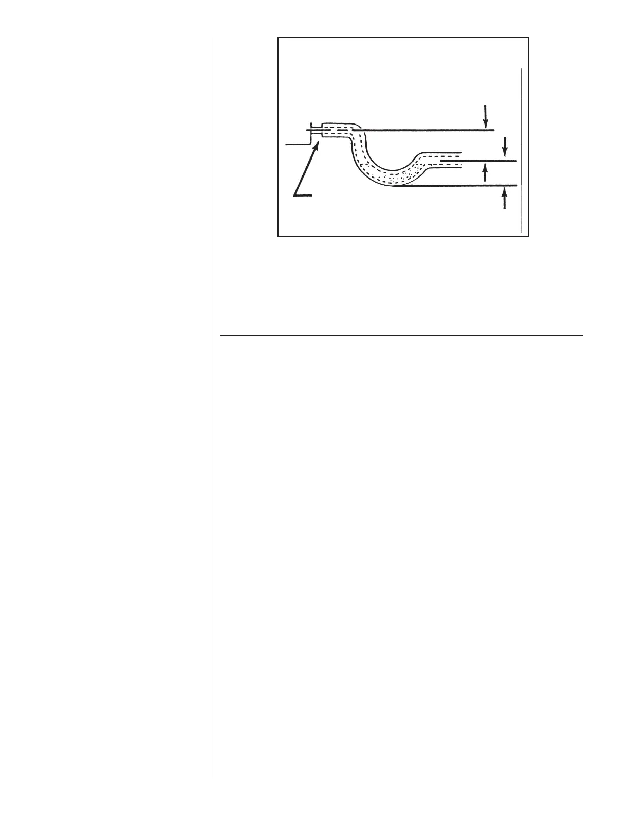
F
IGURE 37
CONDENSATE DRAIN TRAP
DO NOT OPERATE UNIT WITHOUT
CONDENSATE DRAIN TRAP.
UNIT MUST BE SLIGHTLY INCLINED
TOWARD DRAIN CONNECTION.
D
O NOT OVERTIGHTEN DRAIN FITTING
UNIT
3''
3''
 Loading...