26
5.4 COOLING/HEATING AIRFLOW ADJUSTMENTS (-)H1V (SEE FIGURE 25)
Cooling/heating airflow may be adjusted +10% or –10% from nominal airflow using switches 3
and 4.
Refer to Figure 26 for switch positions to achieve the desired adjustments in airflow.
NOTE: Continuous fan speed is NOT affected by switches 3 and 4 selections. Continuous fan
speed is 50% of the selected cooling speed for switches 1 and 2.
IMPORTANT: The use of On Demand Dehumidification overrides the cooling airflow adjust-
ments when high humidity is detected by a dehumidifying thermostat or humidistat when con-
nected to the ODD wire (See Figure 17). Refer to the Cooling Mode Dehumidification section
for more information.
5.5 ELECTRIC HEAT AIRFLOW SETTINGS/ADJUSTMENTS (-)H1V
DIP switches 5 and 6 control electric heat air-flow levels on (-)H1V air-handlers.
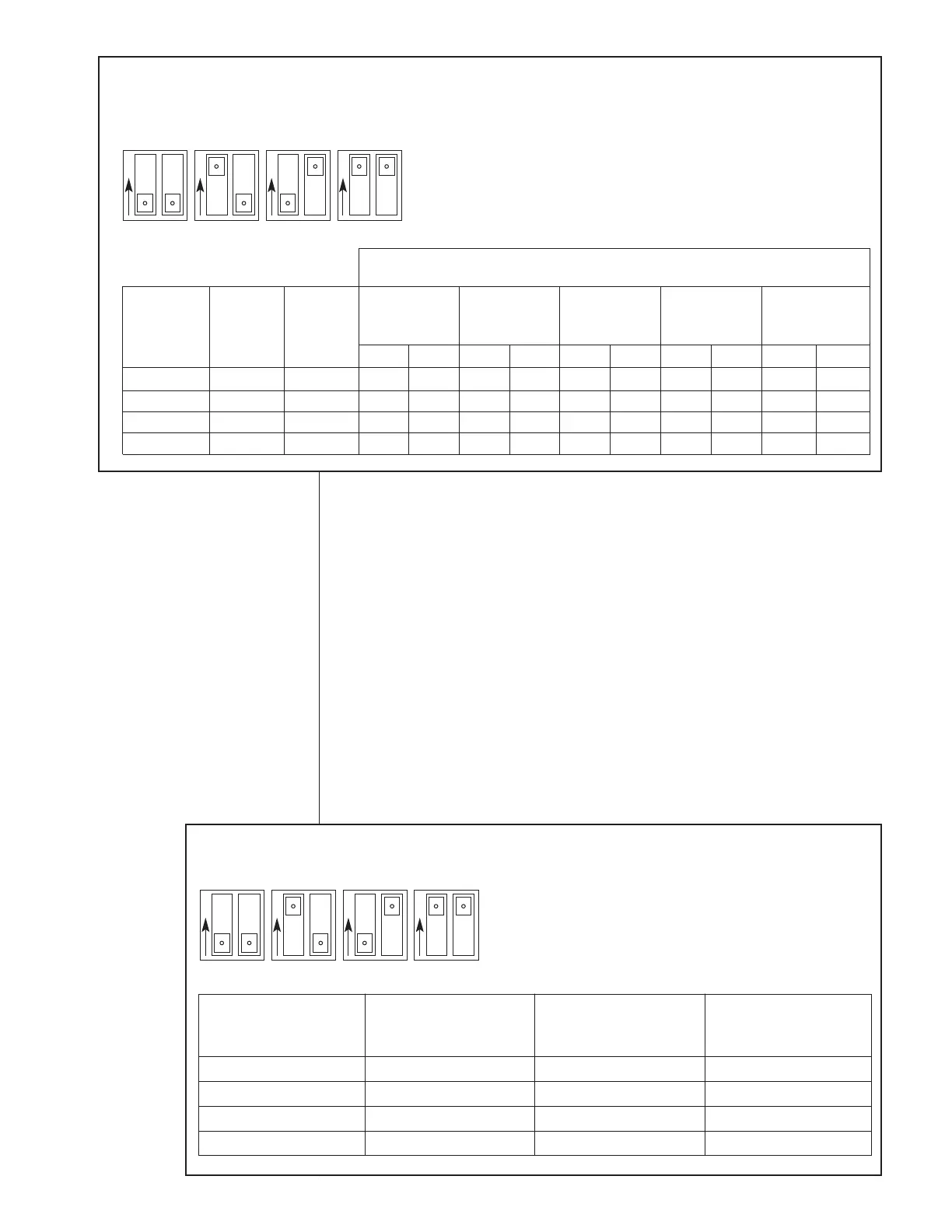
FIGURE 26
COOLING AIRFLOW ADJUSTMENTS (-)H1V
COOLING
SELECTION SWITCH 3 SWITCH 4 AIRFLOW
POSITION POSITION ADJUSTMENT
A OFF OFF NONE
B ON OFF 10%
C OFF ON -10%
D ON ON NONE
O
N
O
N
O
N
O
N
A
3
4
3
4
3
4
3
4
BCD
A OFF OFF 800 800 1200 1200 1600 1600 1800 1800 1725 1725
B ON OFF 800 800 1200 1200 1600 1600 1800 1800 1725 1725
C OFF ON 600 600 1000 1000 1400 1400 1600 1600 1600 1600
D ON ON 600 600 1000 1000 1400 1400 1600 1600 1600 1600
FIGURE 25
FACTORY AIRFLOW SETTINGS FOR SWITCHES 1 AND 2 (-)H1V
SELECTION
(ONE OF THE
PAIRS)
SWITCH 1
AND 5
POSITION
SWITCH 2
AND 6
POSITION
(-)H1V 17/21
1
1
/2 &
2 TON
(-)H1V 17/
2
1
/2 &
3 TON
(-)H1V 21/
3
1
/2 &
4 TON
Y1 Y2 Y1 Y2 Y1 Y2
(-)H1V 24
4
& 5 TON
(-)H1V 21S
4
& 5 TON
Y1 Y1Y2 Y2
COOLING/HEATING AIRFLOW
CABINET SIZE/COOLING CAPACITY
O
N
O
N
O
N
O
N
A
1
2
1
2
1
2
1
2
BCD
N
OTE: With no dehumidification;
switch 9 “ON” (factory default)
– COOLING AIRFLOW
 Loading...