33
6.2 COMFORT CONTROL
2
SYSTEM™ CONTROL BOARD (-)H2V
The (-)H2V series air handler control, Figure 30, has the following features:
• Memory Card – The memory card stores all information needed for unit operation.
Once the system is wired for the Comfort Control
2
, this information is shared with the
thermostat and outdoor unit. This shared data is available if one of the components in
the system needs to be replaced.
• An automotive-style ATC blade fuse for transformer protection (3 amp).
• An on-board LED to indicate blower CFM.
• An RJ-11 port for use with a diagnostic tool.
• Inputs for field installed supply and return air temperature sensors (available in kit
RXHT-A01)
• DIP switches for airflow adjustments
IMPORTANT: The DIP switches are NOT used when the air handler is wired for the
Comfort Control
2
. Airflow adjustments are performed via the thermostat or a diagnostic
tool.
Installation Verification
• Term and bias dip switches should be on.
• 24V AC power on R&C must be present at the control for the air handler to operate,
reference Figure 31.
• Line voltage must be present at the control for indoor blower operation.
• The RX Data LED will flash green in normal operation. A flashing green light indicates
24VAC is present and the data wires 1 and 2 are wired properly.
IMPORTANT: If the RX DATA LED is solid green, data wire 1 and data wire 2 are not
properly connected. Typically, the connections are switched, i.e. data wire 1 is wired to
the data wire 2 connection and data wire 2 is wired to the data wire 1 connection.
Verify wiring and correct the polarity at the two data wires.
IMPORTANT: Diagnostic port is not a phone jack. Connecting to a telephone or tele-
phone system will result in damage.
IMPORTANT: Diagnostic port is for diagnostic tool only. Do not attempt to connect
components using a telephone cord. Damage will occur.
6.3 USING THE ON-BOARD LED TO DETERMINE BLOWER CFM (-)H2V
The CFM LED indicates blower output by flashing one (1) flash for every 100 CFM of air-
flow. The LED will pause 1/10 second between each flash. (See Table 1.)
6.4 AIRFLOW ADJUSTMENTS WITH THE COMFORT CONTROL
2
SYSTEM™
(-)H2V
The RHPN air handler Comfort Control
2
System™ may operate using the Comfort
Control
2
or via traditional thermostat wiring. When the air handler is wired for the
Comfort Control
2
using Data wire 1 and Data wire 2, the DIP switches on the Comfort
Control
2
control have NO affect on the airflow.
IMPORTANT: When using the Comfort Control
2
, the DIP switches have no affect on
airflow or on air handler performance.
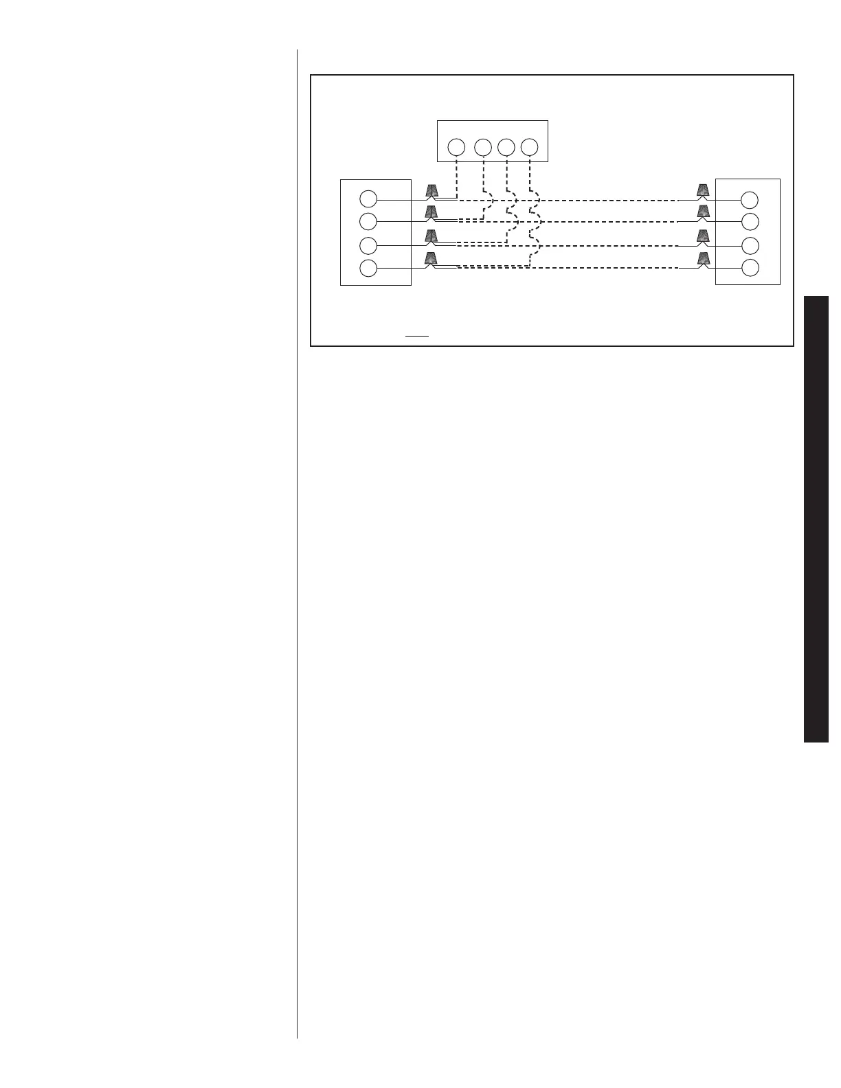
FIGURE 31
TYPICAL COMFORT CONTROL
2
SYSTEM™ WIRING DIAGRAM
Indoor Unit
1
2
C
R
WIRING INFORMATION
L
ine Voltage
–Field Installed - - - - - -
–Factory Standard
1
2
R
C
1
2
R
C
Communicating Thermostat
Outdoor Unit
CONVENTIONAL THERMOSTAT WIRING
 Loading...