42
8.0 REFRIGERANT CONNECTIONS
Keep the coil connections sealed until refrigerant connections are to be made. See the
Installation Instructions for the outdoor unit for details on line sizing, tubing installation,
and charging information.
Coil is shipped with a low (5 - 10 PSIG) pressure charge of dry nitrogen. Evacuate the
system before charging with refrigerant.
Install refrigerant tubing so that it does not block service access to the front of the unit.
Nitrogen should flow through the refrigerant lines while brazing.
Make sure to protect TXV, copper to aluminum joint, and service valves from overheating
by use of wet rag or some type of shielding. Double tip torches are not recommended.
Use a brazing shield to protect the cabinet’s paint from being damaged by torch flames.
After the refrigerant connections are made, seal the gap around the connections with
p
ressure sensitive gasket. If necessary, cut the gasket into two pieces for a better seal.
8.1 TEV SENSING BULB
IMPORTANT: DO NOT perform any soldering with the TEV bulb attached to any line.
After soldering operations have been completed, clamp the TEV bulb securely on the
suction line at the 10 to 2 o’clock position with the strap provided in the parts bag.
Insulate the TEV sensing bulb and suction line with the provided pressure sensitive
insulation (size 4” x 7”) and secure with provided wire ties.
IMPORTANT: TEV sensing bulb should be located on a horizontal section
of suction line, just outside of coil box. The copper sensing bulb must
never be placed on any aluminum tube as this will result in galvanic cor-
rosion and eventual failure of the aluminum tube.
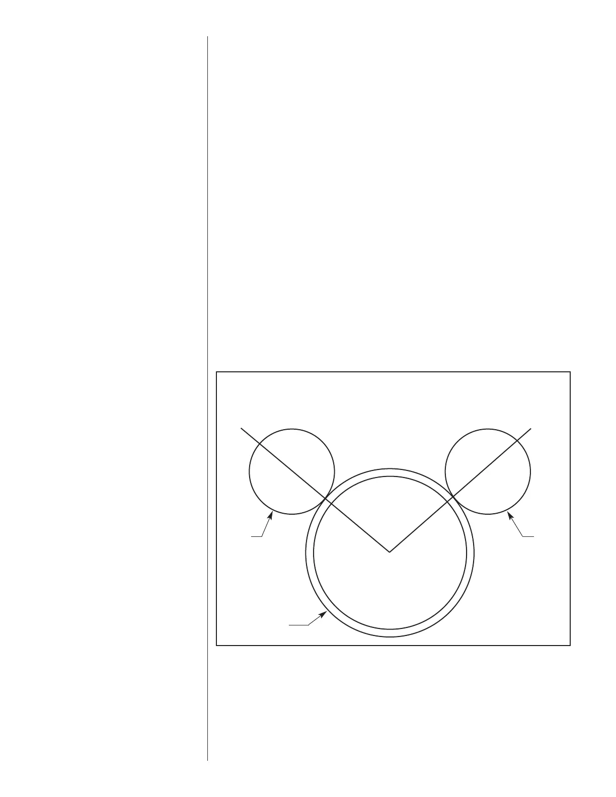
FIGURE 35
BULB LOCATION
10 O’CLOCK 2 O’CLOCK
BULB
VAPOR LINE
BULB
 Loading...