18
4.5 GROUNDING
• Grounding may be accomplished by grounding metal conduit when installed in accor-
dance with electrical codes to the unit cabinet.
• Grounding may also be accomplished by attaching ground wire(s) to ground lug(s)
provided in the unit wiring compartment.
• Ground lug(s) are located close to wire entrance on left side of unit (upflow). Lug(s)
may be moved to marked locations near wire entrance on right side of unit (upflow), if
alternate location is more convenient.
• Use of multiple supply circuits require grounding of each circuit to lug(s) provided in
unit.
!
WARNING
The unit must be permanently grounded. Failure to do so can result in electri-
cal shock causing personal injury or death.
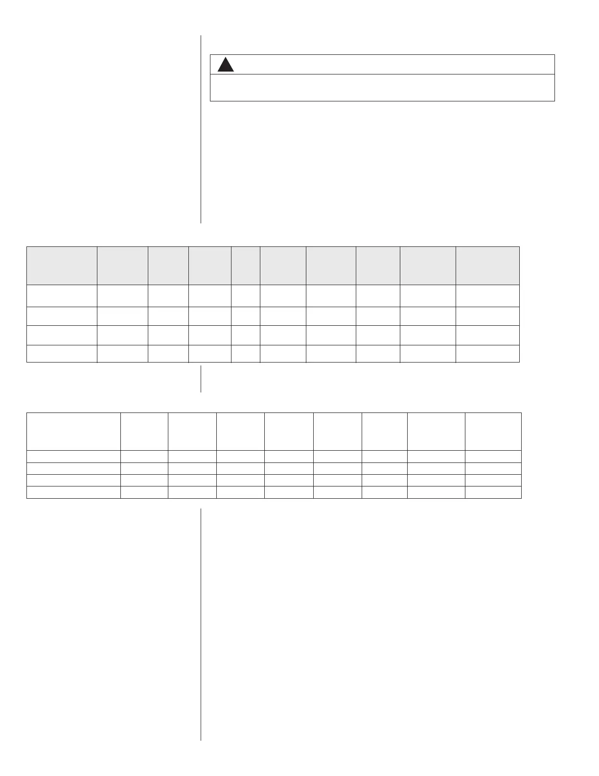
4.6 BLOWER MOTOR ELECTRICAL DATA (-)H1V
MAXIMUM
CIRCUIT
PROTECTOR
MINIMUM
CIRCUIT
AMPACITY
CIRCUIT
AMPS
SPEEDSRPMHPHERTZPHASE
VOLTAGE
MODEL
SIZE
(-)H1V
2417ST 208/240 1 60 1/3 300-1100 2 2.2 3 15
3621H/3617ST 208/240 1 60 1/2 300-1100 2 3.1 4.0 15
4821M/6021S/
208/240 1 60 3/4 300-1100 2 4.0 5.0 15
3621MT/4821ST
6024ST 208/240 1 60 3/4 300-1100 2 4.4 6 15
4.7 BLOWER MOTOR ELECTRICAL DATA (-)H2V
2421HT 1/3 208/230 1 60 300-1100 1.7 4.0 15
3624HT 3/4 208/230 1 60 300-1100 4.9 9.0 15
4824HT 3/4 208/230 1 60 300-1100 4.9 9.0 15
6024HT 3/4 208/230 1 60 300-1100 4.9 9.0 15
(-)H2V HP Voltage Phase Hertz RPM
Circuit
AMPS
Minimum
Circuit
Ampacity
Max. Circuit
Protector
 Loading...