25
INSTALLATION
combustion
air intake
flue gas outlet
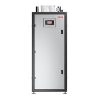
Fig. 20
Flue gas outlet & combustion air intake
DESCRIPTION Array AR SE
ue gas outlet 4" (102mm) Ø
combustion air intake 4" (102mm) Ø
9
WARNING: Read the requirements, instructions and prohi-
bitions detailed below carefully, since non-compliance with
them may be result in substantial property damage, severe
personal injury, death, or the appliance’s malfunction.
9
WARNING: Check that pipes and joints are not damaged.
9
WARNING: Joint seals must be executed with materials that
withstand the condensate’s acidity and the temperatures of
the appliance’s ue gases. They must be approved joint meth-
ods as stated by the vent manufacturer’s installation instruc-
tions for this type of condensing product. Failure to comply
may result in substantial property damage, severe personal
injury or death.
9
WARNING: When installing ue pipes, always bear in mind the
direction of the ue gases and of possible condensate ows.
9
WARNING: Inadequate or incorrectly sized ue gas pipes may
increase combustion noise, create condensate extraction is-
sues and negatively impact on combustion parameters.
9
WARNING: Check that pipes are suitably far (min. 20”) from
ammable liquids.
9
CAUTION: Make sure that condensation is not built up along
the exhaust ue pipe. For this purpose, provide a slope of at
least 3 degrees towards the appliance in horizontal sections.
In case of cascade application, if the horizontal or vertical sec-
tion is longer than 13ft (10m) in a cascade vent application,
a condensate siphon drain must be provided at the base of
the pipe. The height of the siphon must be at least equal to
the value “H” (see gure below). The siphon discharge must
then lead to a drain with an air gap between drain and the
condensate trap. (See section “Preparation for the condensate
drain”
9
WARNING: It is prohibited to block or section the ue gas ex-
haust pipe or the combustion air intake pipe, if any.
0
WARNING: It is prohibited to use condensate pipes that are
not designed for this application, as the condensates acidity
would damage them quickly.
3.14 Gas Type Conversion
The heating unit is factory preset for operating with natural gas.
This set-up can be changed using the conversion kits supplied by
the manufacturer, on demand.
9
DANGER: To prevent risks of personal injury and proper-
ty damage, this conversion shall only be performed by
a trained and certied installer in accordance with the
manufacturer’s instructions and all applicable codes
and requirements of the authority having jurisdiction.
If the information in these instructions is not followed exactly, or
the installation, adjustment, modication, operation or main-
tenance is carried out by an unqualied person, a re, explo-
sion or generation of excessive levels of carbon monoxide may
result causing property damage, personal injury or loss of life.
Before carrying out electrical work, disconnect the appli-
ance from the power supply at the emergency shutoff switch
or by disengaging the heating system circuit breaker. Take
appropriate measures to prevent accidental reconnection.
The installer is responsible for the proper conversion of this
appliance. The conversion is not complete until the operation
of the converted appliance is checked as specied in these
instructions.
The gas-air ratio must always be set on the basis of a CO
2 or O2
reading taken at maximum nominal output and minimum nomi-
nal output using an electronic ue gas analyzer. The desired high-
re excess O2 level is 5.1% for natural gas.
Natural Gas to Propane Conversion Kit for AR 399 SE: Part #20185234
Natural Gas to Propane Conversion Kit for AR 500 SE: Part #20185235
Switching from NATURAL GAS to LP
− Close the gas shutoff valve
− Disconnect the electric power supply from the boiler
9
WARNING: To avoid electrical shock, it is mandatory to discon-
nect the boiler from the power supply using an external cir-
cuit breaker or disconnect switch.
− Open the front panels
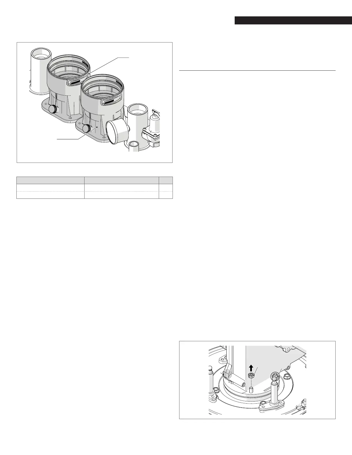
− Change the mixer with new version present in the Conver-
sion specic Kit.
− Unscrew the nuts (1) that connect the fan to the upper
ange of the heat exchanger
1
1
1
Fig. 21
NG mixer removal
 Loading...