26
INSTALLATION
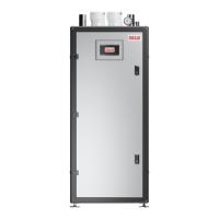
− remove the tube (2), that connects the mixer and the gas
valve
2
Fig. 22
NG mixer removal
− remove screws (3) in order to get out the mixer
3
3
Fig. 23
NG mixer removal
− connect the LPG mixer (4) to the fan, putting in the O-ring
(5) and screws (6)
4
5
6
6
Fig. 24
LPG mixer installation
− reassemble the fan unit and the mixer by reversing the pre-
vious operations.
− Use the PB inner display to enter the appliance congura-
tion menu and change the parameters #97 and #98:
Model
LPG
AR 399 SE AR 500 SE
Par. 97 22 22
Par. 98 84 82
− Adjust the O
2 parameter as explained in next chapter
− Afx the gas type label from the gas conversion kit to the
appliance.
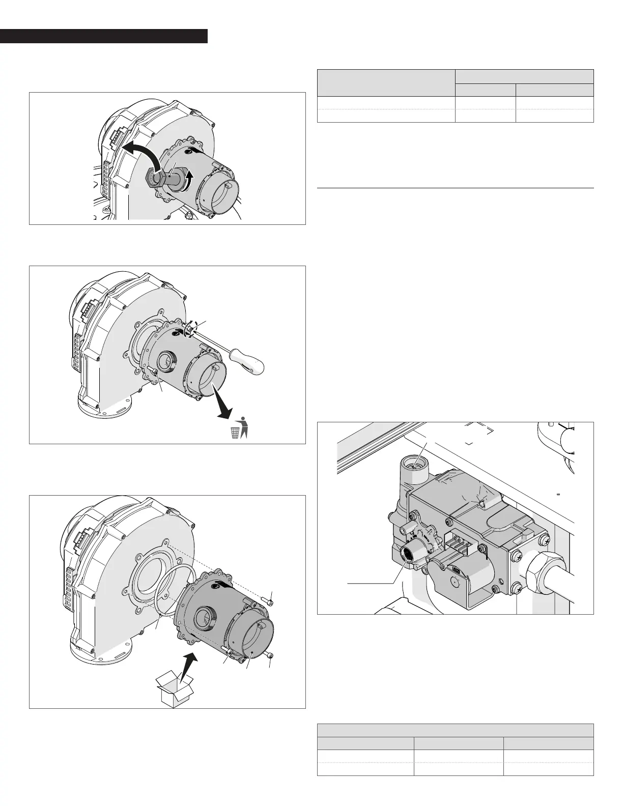
3.15 Adjusting and Setting O2 Limits
− Insert a combustion analyzer probe into the test port;
− Go to the Touchscreen and access the Module screen rele-
vant to the module under analysis;
− Press “MODULE TEST” button;
− Press “HIGH POWER” button.
Wait 2 or 3 minutes to reach steady state conditions and record
the O
2 value.
To adjust the O
2 value at high-re turn the screw “A” (rotate count-
er-clockwise to decrease O
2) . An allen type wrench is necessary for
this adjustment.
Verify that the value of O
2 is stable and within the range indicat-
ed in the following table (be careful to make small changes and
conrm that the value is stable before making additional adjust-
ment).
Press “LOW POWER”: the fan will run at the minimum speed.
To adjust the O
2 value at the minimum input, turn the screw “B”
(rotate clockwise to decrease O
2)
Screw “B”
Screw “A”
Fig. 25
Adjusting O
2
Verify that the value of O2 is stable and within the range indicat-
ed in the following table (be careful to make small changes and
conrm that the value is stable before making additional adjust-
ment).
Press “Reset” and the boiler return to the “stand by” mode.
Press “Reset” to return the boiler to standby mode.
Repeat above process for all heat exchangers.
Array Combustion Values
Gas Type Max. Fire O
2% Min. Fire O2%
Natural Gas 4.2 – 5.8 4.2 – 5.8
LP Gas 5.0 - 5.6 5.0 - 5.6
 Loading...