57
RECYCLING AND DISPOSAL
57
APPENDIX
APPENDIX
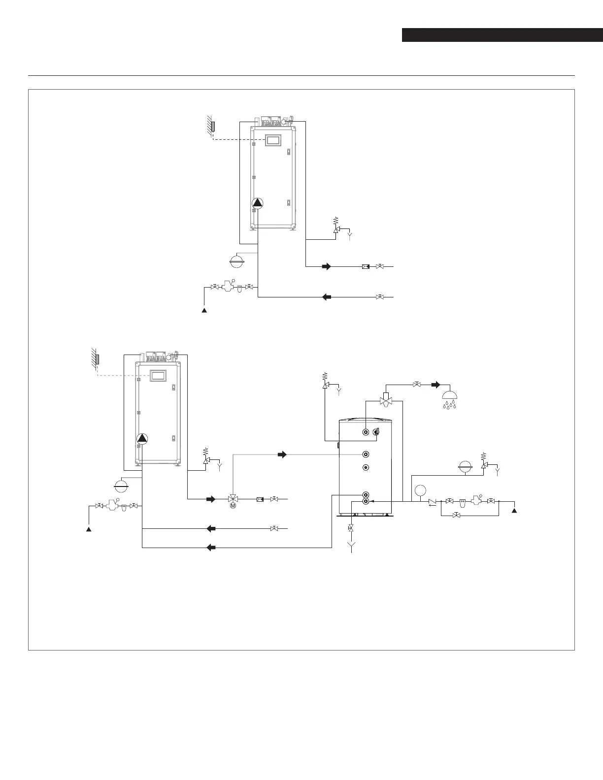
APPENDIX F - TYPICAL WATER SYSTEM SCHEMATICS
Layout 1: circuit with boiler directly linked to heating system (check that the pump's discharge head is sufcient to ensure ade-
quate circulation)
4
11
8 7
2
1
RI
1
11
OS
5
6
Layout 2: circuit with boiler directly linked to heating system and indirect DHW tank. (check that the pump's discharge head is
sufcient to ensure adequate circulation)
1
UAC
3
EAF
4
M
2 7
8
1 1
1
1
9
5
6
5
6
10
8 7
EAF
MI
2
1
RI
1
11
OS
11
5
6
4
OS Outdoor temperature
sensor
MI High temperature system
supply
RI High temperature system
return
EAF Domestic cold water inlet
UAC Domestic hot water outlet
9
WARNING: Domestic hot water and central heating circuits
must be completed with expansion tanks of adequate ca-
pacity and suitability, correctly-sized pressure relief valves.
The discharge of pressure relief valves and appliances must be
connected to a suitable collection and disposal system.
9
CAUTION: The choice of system components and the method
of their installation are left up to the heating engineer install-
ing the system. Installers must use their expertise to ensure
proper installation and functioning in conformity to all appli-
cable legislation.
9
CAUTION: Special supply/rell water must be conditioned using
suitable treatment systems.
0
WARNING: It is prohibited to operate the boiler without water.
1 Isolating valve
2 Check valve
3 Anti-scald mixing valve
4 Expansion tank
5 Pressure relief valve
6 Drain
7 Water softener lter
8 Pressure reducer
9 Domestic water storage tank
10 Diverter valve
11 Pump
 Loading...