Rockwell Automation Publication 440R-UM013F-EN-P - July 2021 27
Chapter 3 Power, Ground, and Wire
Auxiliary Output Each safety relay has an auxiliary output. The auxiliary output is not a safety
rated output; it is a low current output that is designed to indicate that the
safety output status is OFF. The auxiliary output is in the opposite state of the
safety outputs. When the safety outputs are ON, the auxiliary output is OFF.
When the safety outputs are OFF, the auxiliary output is ON.
When the EM and EMD safety relays are in a faulted state, the auxiliary
outputs are in an OFF state because the auxiliary outputs are often used as the
source of the monitoring circuit. If the EM or EMD safety relays are faulted,
the safety system must not reset until the fault is corrected.
The DI, DIS, EM, EMD, and SI safety relays have a solid-state transistor
auxiliary output. The CI safety relay has an electromechanical output. Table 3
summarizes the terminal connections of the auxiliary output.
Reset and Monitor Input The CI, DI, DIS, and SI safety relays have a reset/monitoring input (terminal
S34). The expansion safety relays (EM and EMD) do not have a reset input.
The reset action can be configured for either automatic or manual reset. When
the relay is configured for automatic reset, the safety relay outputs turn ON as
soon as the safety inputs are closed if terminal 34 is connected to 24V. If a
normally open switch is placed in the circuit, the reset function occurs on the
leading edge (when the switch is pressed).
When the relay is configured for manual reset, the safety relay outputs turn
ON after the inputs are closed and then the reset input is cycled from OFF to
ON and then back OFF again.
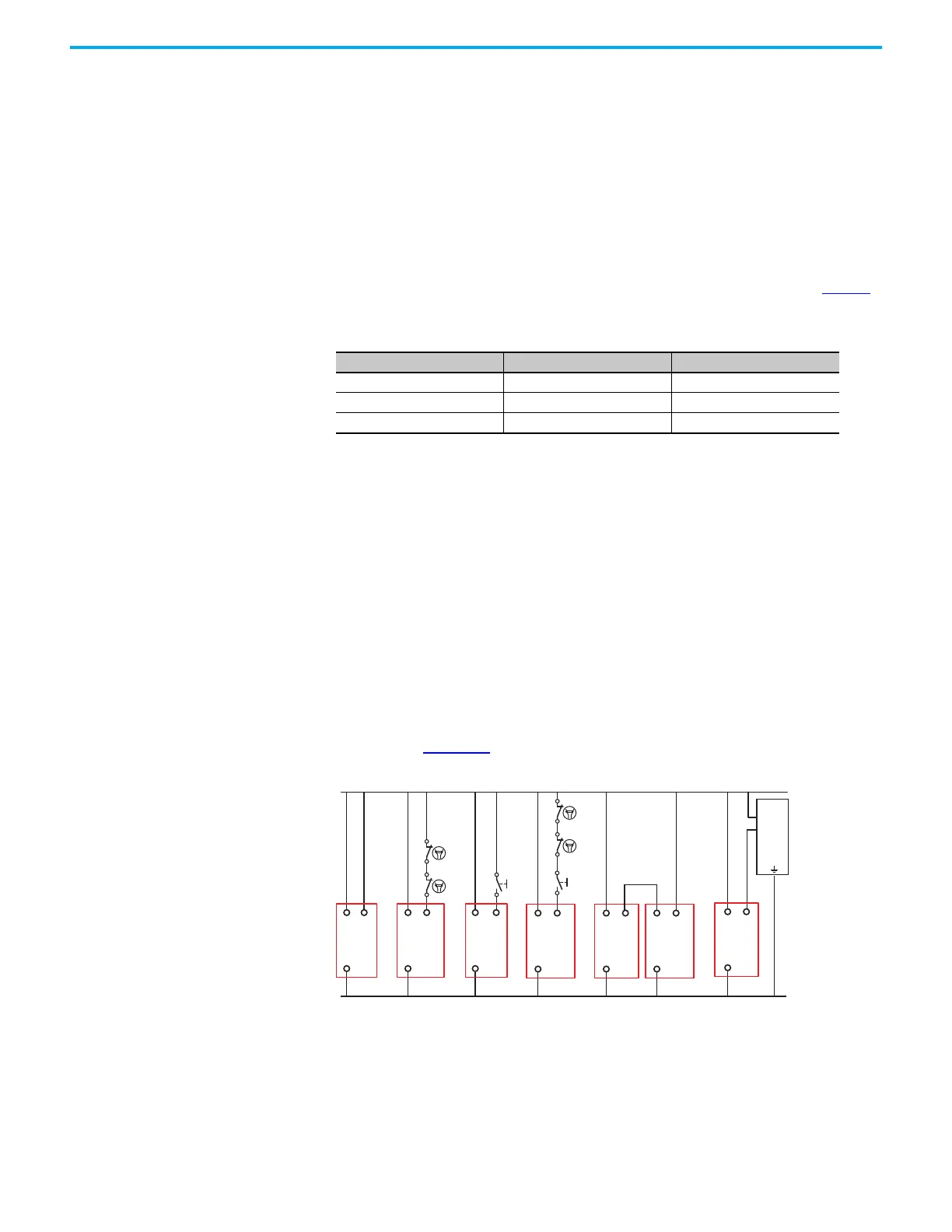
Monitoring of external devices, like safety control relays and safety contactors,
can be accomplished by adding normally closed contacts in series with the
reset signal. Figure 20
shows typical reset/monitoring circuits.
Figure 20 - Typical Reset/Monitoring Circuits
Table 3 - Auxiliary Outputs
Relay Type of Output Terminal Connections
CI Electromechanical 41/42
DI, DIS, SI Transistor Y32
EM, EMD Transistor X32
+24V DC
24V DC Com
S34A1
A2
12
34 5 6
S34A1
A2
S34A1
A2
S34A1
A2
+
1
2
3
PLC
S34A1
A2
S34A1
A2
A1
A2
Circuit
Circuit Circuit Circuit Circuit Circuit
EM or
EMD
 Loading...


