Rockwell Automation Publication 440R-UM013F-EN-P - July 2021 45
Chapter 9
Application and Wiring Examples
The application and wiring examples in this chapter show you how to put the
inputs and outputs together to create an operating safety system. These circuit
diagrams are examples; many features are interchangeable between relays.
Publication SAFETY-WD001
provides additional application and wiring
diagrams.
CI Safety Relay
(Cat.No.440R-S13R2)
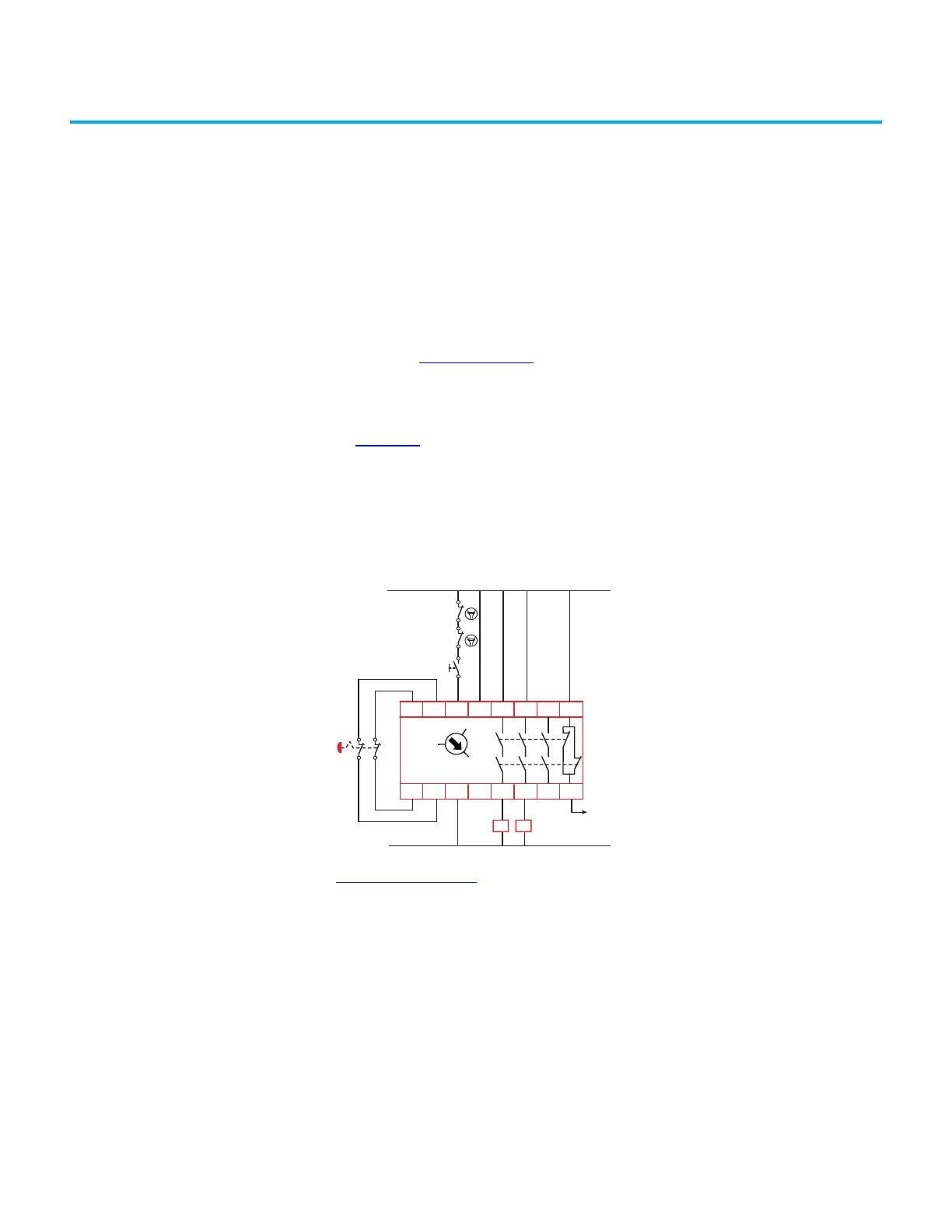
In Figure 42, the CI safety relay is monitoring a device (an E-stop push button)
with mechanically operated contacts. The CI safety relay is configured for
monitored manual (MM) reset. The output turns on if the E-stop is released
and the reset push button is pressed and released between 0.25…3 seconds. The
CI safety relay monitors the status of the two output contactors, K1 and K2. If
either fails to close their N.C. contacts, the CI safety relay does not reset. An
auxiliary signal, terminals 41/42, is sent to the PLC when the E-stop is pressed.
Figure 42 - Mechanical Contacts with Monitored Manual Reset
Figure 43 on page 46 shows a CI safety relay monitoring a light curtain with
two OSSD outputs. The CI safety relay is set to automatic/manual reset (AM).
The auxiliary signal (terminals 41/41) informs the PLC that the safety system is
OFF or ON. The CI safety relay outputs connect to AC voltage loads. When the
CI safety relay is ON, the PLC can then turn on the K1 and K2 contactors.
S11
S12
S21
S22
S34 A1 13
L11A2 14
23
24
33 41
34 42
CI
440R-S13R2
0
MM
AM
K1
24V DC
24V Com
K2
K1 K2
 Loading...


