Rockwell Automation Publication 440R-UM013F-EN-P - July 2021 69
Chapter 11 Troubleshooting
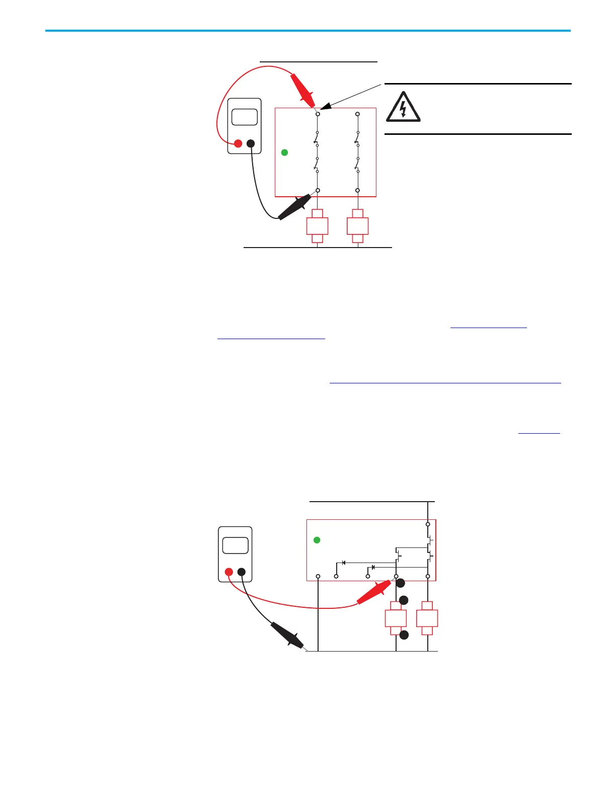
Figure 77 - Measure the Contact Resistance
OSSD Output Issues
If the OUT status indicator is steady green, but the output device that is
connected to terminal 14 or 24 does not energize, begin troubleshooting by
checking the voltage at the output connections. See Check the OSSD
Connections on page 69.
If the OUT status indicator is steady green, but the PowerFlex™ drive is
providing indication that the safety circuit is open, check the connections to
the PowerFlex drive. See Check the PowerFlex Drive Connections
on page 70.
Check the OSSD Connections
Confirm that voltage is present at the relay terminals and the load. Figure 78
shows an example of the measurement points for one output channel
(terminal 14). Since most safety circuits consist of two channels, repeat the
checking on the second channel (terminal 24).
Figure 78 - OSSD Output Connections
14
24
<1
13
OUT
23
Ohms
DMM
K1
A2
A1
K2
A2
A1
SHOCK HAZARD: Remove the
power connections to terminal
13 before measuring the
contact resistance.
+V supply
0V
34 44 14 24
A1
A2
23
Volts
DMM
1
OUT
K1
A2
A1
K2
A2
A1
2
3
 Loading...


