24 Rockwell Automation Publication SYSLIB-RM044D-EN-P - February 2017
PowerFlex 753 Drive (P_PF753)
PowerFlex 753 Drive Local Configuration Tags
Configuration parameters that are array, string, or structure data types cannot be
configured as parameters for Add-On Instructions. Configuration parameters of
these types appear as local tags to the Add-On Instruction. Local tags can be
configured through the HMI faceplates or in Studio 5000 Logix Designer®
application by opening the Instruction Logic of the Add-On Instruction instance
and then opening the Data Monitor on a local tag. These parameters cannot be
modified by using controller logic or Logix Designer application export/import
functionality.
Operations
This section describes the primary operations for Add-On Instructions.
Modes
This instruction uses the following standard modes, which are implemented by
using an embedded P_Mode Add-On Instruction.
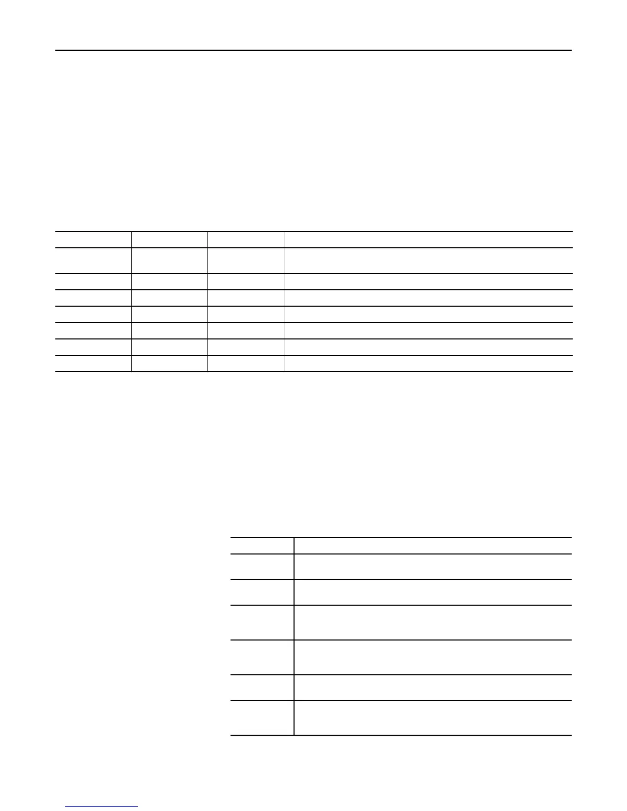
Table 10 - Local Configuration Tags
Tag Name Data Type Default Description
Cfg_Desc STRING_40 'PowerFlex 753 Variable
Frequency Drive'
Description for display on HMI. This string is shown in the title bar of the faceplate.
Cfg_FwdText STRING_16 'Forward' Name for forward direction, for example, ‘Up’, ‘Forward’.
Cfg_Label STRING_20 'Motor Speed Control' Label for graphic symbol displayed on HMI. This string appears on the graphic symbol.
Cfg_RevText STRING_16 'Reverse' Name for reverse direction, for example, ‘Down’, ‘Reverse’.
Cfg_SpeedFdbkEU STRING_8 'Hz' Speed feedback engineering units for display on HMI.
Cfg_SpeedRefEU STRING_8 'Hz' Speed reference engineering units for display on HMI.
Cfg_Tag STRING_20 'P_PF753' Tag name for display on HMI. This string is shown in the title bar of the faceplate.
Table 11 - Modes
Mode Description
Operator The Operator owns control of the device. Operator commands (OCmd_) and Operator settings
(OSet_) from the HMI are accepted.
Program Program logic owns control of the device. Program commands (PCmd_) and Program settings
(PSet_) are accepted.
Override Priority logic owns control of the device and supersedes Operator and Program control. Override
Inputs (Inp_OvrdCmd and other Inp_OvrdXxxx values) are accepted. If so configured,
bypassable interlocks and permissives are bypassed.
Maintenance Maintenance owns control of the device and supersedes Operator, Program, and Override
control. Operator commands and settings from the HMI are accepted. Bypassable interlocks and
permissives are bypassed, and device timeout checks are not processed.
Hand Hardwired logic or other logic outside the instruction owns control of the device. The instruction
tracks the state of the device for bumpless transfer back to one of the other modes.
No Mode The device is disabled and has no owner because the EnableIn input is false. The main
instruction Logic routine is not being scanned. See Execution section for more information on
EnableInFalse processing.

 Loading...