Rockwell Automation Publication SYSLIB-RM044D-EN-P - February 2017 19
PowerFlex 753 Drive (P_PF753)
PowerFlex 753 Drive Output Structure
Output parameters include the following:
• Output data elements (Out_) are the primary outputs of the instruction,
typically used by hardware output modules; however, they can be used by
other application logic.
• Value data elements (Val_) are numeric outputs of the instruction for use
by the HMI. Values can also be used by other application logic or software
packages.
• Source and Quality data elements (SrcQ_) are outputs of the instruction
used by the HMI to indicate PV source and quality.
• Status data elements (Sts_) are bit outputs of the instruction for use by the
HMI. Status bits can also be used by other application logic.
• Error data elements (Err_) are outputs of the instruction that indicate a
particular configuration error. If any Err_ bit is set then the Sts_Err
configuration error summary status is set and the Invalid Configuration
indicator is displayed on the HMI.
• Not Ready data elements (Nrdy_) are bit outputs of the instruction for use
by the HMI for displaying the Device Not Ready indicator.
• Alarm data elements (Alm_) are outputs of the instruction that indicate a
particular alarm has occurred.
• Acknowledge data elements (Ack_) are outputs of the instruction that
indicate the corresponding alarm has been acknowledged.
• Ready data elements (Rdy_) are bit outputs of the instruction used by the
HMI to enable or disable Command buttons and Setting entry fields.
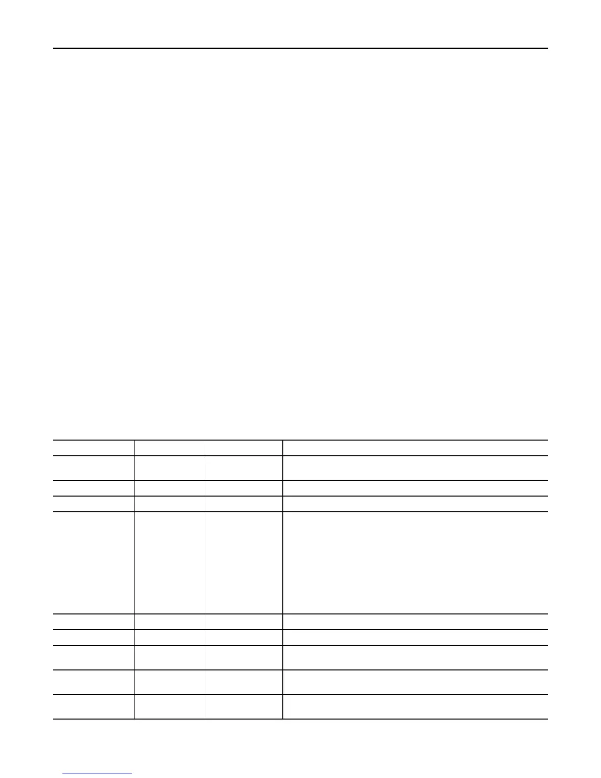
Table 9 - P_PF753 Drive Output Parameters
Output Parameter Data Type Alias For Description
EnableOut BOOL Enable Output: The EnableOut signal is not manipulated by this instruction. Its output state
always reflects EnableIn Input state.
Val_SpeedRef REAL Speed Reference (target) to drive.
Val_SpeedFdbk REAL Speed Feedback (actual) from drive.
Val_SpeedRefSrc DINT Speed Reference Source (enumeration)
1 = Reference A
2 = Reference B
3 = Preset 3
4 = Preset 4
5 = Preset 5
6 = Preset 6
7 = Preset 7
16…31 = Manual Reference Settings
Val_SpeedRefRaw REAL Copy of Speed Reference Output (in Raw units) for faceplate.
Val_SpeedFdbkRaw REAL Copy of Speed Feedback Input (in Raw units) for faceplate.
Val_SpeedRefEUMin REAL Minimum of Speed Reference = MIN (Cfg_SpeedFdbkEUMin, Cfg_SpeedFdbkEUMax).
(engineering units)
Val_SpeedRefEUMax REAL Maximum of Speed Reference = MAX (Cfg_SpeedFdbkEUMin, Cfg_SpeedFdbkEUMax).
(engineering units)
Val_SpeedFdbkEUMin REAL Minimum of Speed Feedback = MIN (Cfg_SpeedFdbkEUMin, Cfg_SpeedFdbkEUMax).
(engineering units)

 Loading...