23
Apr. 2000 VG-88
ERROR MESSAGES
/エラーメッセージ
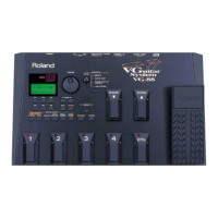
TEST : 6.BATTERY
If the battery voltage for memory back-up is "2.7V" or less, the
display shows "BATTERY LOW !".
◎TEST : 6.BATTERY
2.7V 以下の場合は「BATTERY LOW !」を表示します。
If no battery connected, the display shows "NO BATTERY !".
バッテリーが装着されていない場合 は「NO BATTERY !」を表
示します。
∗
Replace with a new lithium battery of the same type. If the
error condition still exists, check the following parts and
associatd wirings.
*新しいリチウム電池を挿入してください。新しいリ チウム電
池を挿入してもエラーメッセージが出る場合には次 のパーツ
およびその配線をチェックしてください。
CPU(IC1) : pin 26
OP.Amp(IC3) : pins 1-5
Resistor(R1, R2, R4)
Diode(D1)
Capacitor(C4,C8)
SRA<(IC2, IC4):pin 32
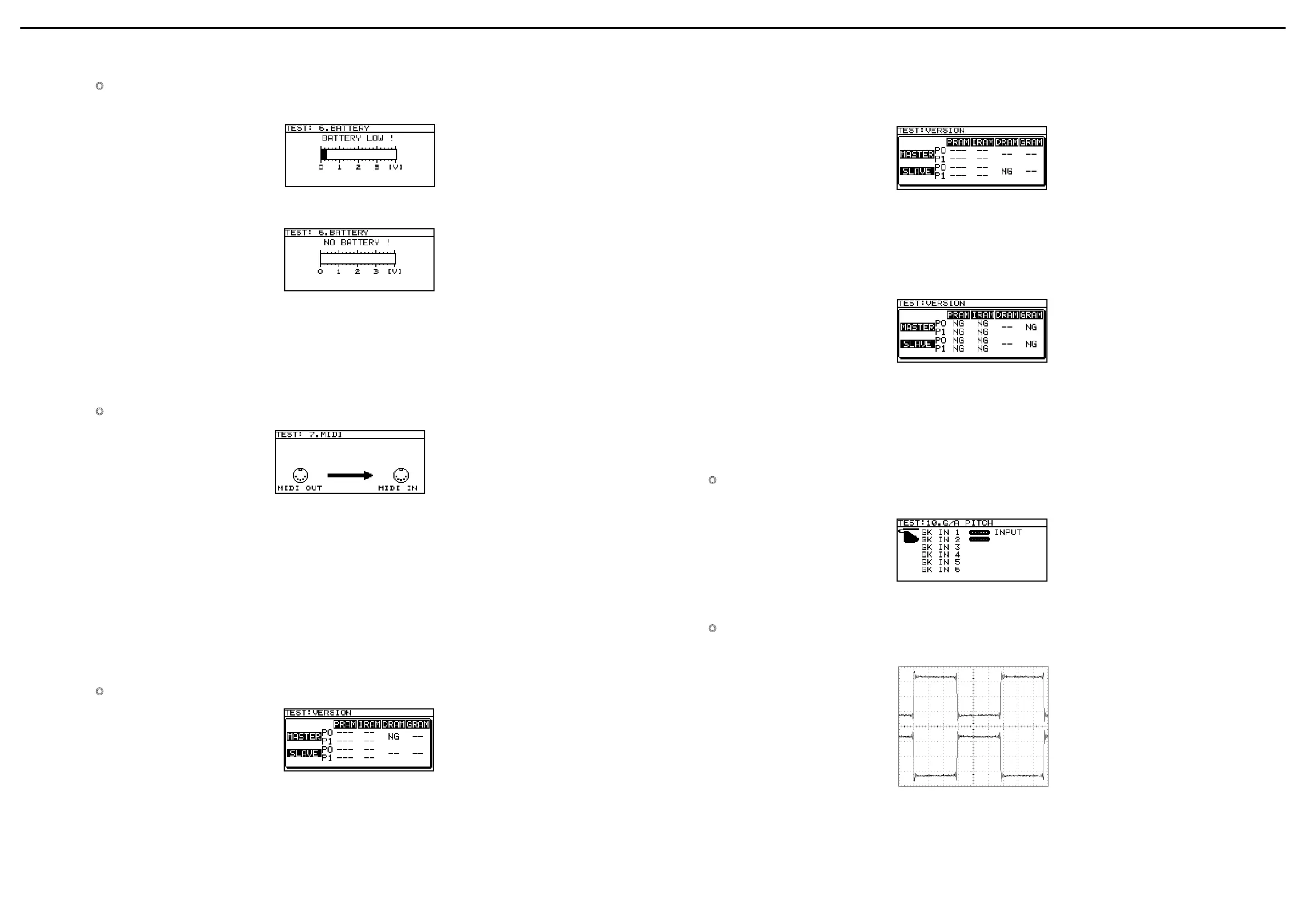
TEST : 7.MIDI
◎TEST : 7.MIDI
Symptom : No connect MIDI IN jack to MIDI OUT jack via the
MIDI cable.
Symptom : Transmitted data (MIDI OUT) and received data
(MIDI IN) don't agree with eack other.
∗
Check the following parts and assosiated wirings.
症状:MIDI ケーブルが接続されていません。
症状:送信したデータ (MIDI OUT) と受信したデータ (MIDI IN
が一致しない。
*次のパーツおよび配線をチェックしてください。
MIDI IN
CPU(IC1) : pin 40
Resister(R19,R20,R21)
Capacitor(C13)
Photo Coupler(IC9)
Diode(D1)
MIDI OUT
CPU(IC1) : pins 38,39
Resister(R9,R11,R13-R15)
Gate IC(IC7):pins 1-4
Transistor(Q1)
Inductor(L1,L2)
TEST : DSP CHECK (After TEST:8.GK VOL)
◎TEST : DSP CHECK (TEST: 8.GK VOL 終了後 )
Symptom :DRAM(IC16) returns data which is different from that
written to it through DSP(IC13).
∗
Check the following parts and assosiated wirings.
症状:DSP(IC13) を通して DRAM(IC16) に書き込んだデータと
読み出したデータが一致しない。
*次のパーツおよび配線をチェックしてください。
DATA : DSP(IC13) :
pins 7-10, 32-35
↔DRAM(IC16) :
pins 2-10
ADDRESS : DSP(IC13) : pins 16-26
↔
DRAM(IC16) : pins 16-19, 22-26
WE : DSP(IC13) : pin 13
↔
DRAM(IC16) : pin 13
CAS : DSP(IC13) : pin 14
↔
DRAM(IC16) : pin 29
RAS : DSP(IC13) : pin 15
↔
DRAM(IC16) : pin 14
Symptom :DRAM(IC15) returns data which is different from that
written to it through DSP(IC12).
∗
Check the following parts and assosiated wirings.
症状: DSP(IC12) を通して DRAM(IC15) に書き込んだデータと
読み出したデータが一致しない。
*次のパーツおよび配線をチェックしてください。
DATA : DSP(IC15) : pins 7-10, 32-35
↔
DRAM(IC12) : pins 2-10
ADDRESS : DSP(IC15) : pins 16-26
↔
DRAM(IC12) : pins 16-19, 22-26
WE : DSP(IC15) : pin 13
↔
DRAM(IC12) : pin 13
CAS : DSP(IC15) : pin 14
↔
DRAM(IC12) : pin 29
RAS : DSP(IC15) : pin 15
↔
DRAM(IC12) : pin 14
Symptom : GATE ARRAY(IC11) returns data which is different
from that written to it through DSP(IC12,13).
∗
Check the following parts and assosiated wirings.
症状: GATE ARRAY(IC11) を通して DSP(IC12,13) に書き込ん
だデータと読み出したデータが一致しない。
*次のパーツおよび配線をチェックしてください。
GATE ARRAY(IC11) : pins 21-34
↔
DSP(IC12):pins 74-88
↔
DSP(IC13):pins 74-88
GATE ARRAY(IC11) : pins 11-20
↔
DSP(IC12):pins 92-99
↔
DSP(IC13):pins 92-99
GATE ARRAY(IC11) : pin 41
↔
DSP(IC13):pin 68
GATE ARRAY(IC11) : pin 42
↔
DSP(IC12):pin 68
GATE ARRAY(IC11) : pin 44
↔
DSP(IC12):pin 69
↔
DSP(IC13):pin 69
GATE ARRAY(IC11) : pin 43
↔
DSP(IC12):pin 70
↔ DSP(IC13):pin 70
TEST : 10.G/A PITCH
Symptom : The pitch data of GATE ARRAY(IC11) is not correct.
◎TEST : 10.G/A PITCH
症状: GATE ARRAY(IC11) から得られるピッチ情報が正しく
ない。
∗
Check the following parts and assosiated wirings.
*次のパーツおよび配線をチェックしてください。
GATE ARRAY(IC11) : pin 94
↔
CPU(IC1) : pin 4
TEST : 11.OUTPUT
Symptom :The waveform is not shown as below on the
oscilloscope.
◎TEST : 11.OUTPUT
症状: オシロスコープの波形が下図と異なる。
∗
Check the following parts and assosiated wirings.
*次のパーツおよび配線をチェックしてください。
CPU(IC1) : pin 76, Resister(R23-R25,R161-R165),Diode(D2),Capacitor(C22),Transister(Q2-Q7)
 Loading...