EasyManua.ls Logo

S&C Vista SD User Manual

S&C Vista SD
37 pages
To Next Page IconTo Next Page
To Previous Page IconTo Previous Page
Page #24 background imageLoading...
Page #24 background image
24 S&C Instruction Sheet 695-510
Maintenance
Figure 40. Install the new shear pin.
Figure 41. Install a retaining ring on the opposite side of the
shear pin.
Figure 42. Rotate the actuator with a screwdriver until the
latching mechanism closes.
Figure 43. Secure the enclosure with a padlock.
STEP 6. Install one of the retaining rings on one end of the
new shear pin. Insert the shear pin into the hole on
the side of the latch drive. The pin should go com-
pletely through the latch drive and pentahead plug.
See Figure 40.
STEP 7. Rotate the latch drive 180° and install the retaining
ring on the opposite end of the shear pin.
See Figure 41.
STEP 8. Insert a pentahead socket wrench or tool into the
pentahead socket, and rotate it 360° counterclock-
wise. The mechanism should operate the latch
smoothly through its full rotation and stop on
reaching 36.
STEP 9. Close and secure the hinged roof per the instruc-
tions in “Closing the Doors and the Hinged Roof” on
Page 14.
Closing and Securing the Enclosure if
Replacement Shear Pin is Unavailable
If the shear pin is broken and the enclosure needs to be opened
for switching, and a replacement shear pin is unavailable, the
enclosure can be easily closed and secured by following these
steps:
STEP 1. Open the enclosure using the instructions de-
scribed in “Replacing the Enclosure Latch Shear
Pin” on page 23. Retain the pentahead plug and
shim washer in a secure area. Perform any neces-
sary switching.
STEP 2. Close the hinged roof of the switchgear.
STEP 3. Using a long-handled screwdriver, insert the blade
of the screwdriver into one of the pin holes inside
the actuator. Brace the screwdriver against the rim
of the socket. Using the screwdriver like a handle,
turn the screwdriver 360° clockwise to close and
latch the hinged roof. See Figure 42.
STEP 4. Insert a padlock shackle through the hole in the
padlock recess and lock the padlock. See Figure 43.

Other manuals for S&C Vista SD

Question and Answer IconNeed help?

Do you have a question about the S&C Vista SD and is the answer not in the manual?

S&C Vista SD Specifications

General IconGeneral
BrandS&C
ModelVista SD
CategorySwitch
LanguageEnglish

Summary

Introduction

Qualified Persons

Defines requirements for personnel qualified to install, operate, and maintain switchgear.

Instruction Sheet Guidance

Emphasizes the importance of reading and keeping the instruction sheet for reference.

Proper Application and Warranty

Details correct application of equipment and warranty terms and conditions.

Safety Information

Understanding Safety Alert Messages

Explains signal words like DANGER, WARNING, CAUTION, and NOTICE used in the manual.

Safety Label Locations

Illustrates the placement of critical safety labels on the switchgear units.

Safety Precautions

General Electrical Safety Procedures

Lists 12 essential safety precautions for operating high-voltage switchgear.

Components

Switchgear Component Descriptions

Describes the features and types of load-interrupter switches and fault interrupters.

Visual Component Identification

Provides diagrams identifying key components of vault-mounted and pad-mounted switchgear.

Operation

Manual Operation of Switches and Interrupters

Details the procedure for manually opening and closing switches and fault interrupters.

Pad-Mounted Enclosure Access

Step-by-step guide for opening doors and the hinged roof of pad-mounted units.

Closing Doors and Hinged Roof

Procedure for correctly closing and securing the enclosure doors and hinged roof.

Resetting Fault Interrupters

Procedure for resetting Visi-Gap fault interrupters after a fault.

Locking Switches in Position

Instructions for padlocking load-interrupter switches or fault interrupters.

Checking Voltage with Potential Indicator

How to test for voltage presence using the optional potential indication feature.

Low-Voltage Phasing Procedure

Steps for performing low-voltage phasing using the voltage indication feature.

Maintenance

Inspecting Cable Terminations

Procedure for visual inspection and temperature measurement of cable terminations.

Pad-Mounted Enclosure Finish Care

Guidelines for touch-up and cleaning of the enclosure finish.

Replacing Enclosure Latch Shear Pin

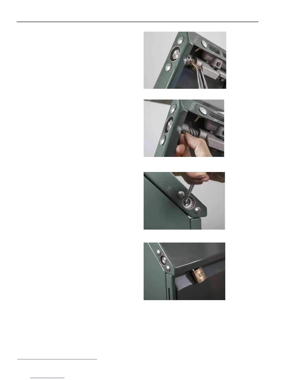
Detailed steps for replacing a broken shear pin in the enclosure latch mechanism.

Securing Enclosure Without Shear Pin

Procedure to secure the enclosure if a replacement shear pin is unavailable.

Appendix A

Routine Switchgear Testing

Information on performing routine insulation and withstand tests on switchgear.

DC Cable Testing and Fault Locating

Guidance on DC testing methods for cables and locating faults.

VLF Cable Testing

Details on performing Very Low Frequency (VLF) testing on cable systems.

Fault-Interrupter Testing

Guidelines for dielectric testing of fault interrupters.

Appendix B

Switchgear and Component Ratings

Presents electrical ratings for Vista SD switchgear, load-interrupter switches, and fault interrupters.

Appendix C

Switchgear Styles and Models

Table detailing available switchgear styles and their corresponding catalog number suffixes and models.

Appendix D

Optional Features and Configuration

Lists optional features that can be added to switchgear assemblies and their catalog number suffixes.

Appendix E

Accessories and Kits

Catalog numbers for accessories such as shotgun clamp sticks and remote control pendants.

Appendix F

Replacement Parts Information

Lists catalog numbers for replacement parts like bushing adapters and tools.

Appendix G

Touch-Up Kit Components

Catalog numbers for touch-up paint colors and primers for enclosure finish.

Appendix H

Auxiliary Contacts Connector Pinout

Diagram and function list for the auxiliary contacts receptacle connector pins.

Related product manuals