S&C Instruction Sheet 695-510 25
Appendix A
Routine Switchgear Testing
For the convenience of users who normally perform electrical
tests on system components such as switchgear, appropriate
withstand test values for Vista SD Underground Distribution
Switchgear are given in Table 1 and Table 2 on page 26. These
test values are signicantly greater than the normal operating
voltage of the switchgear and are near the ashover voltage
of the switchgear. They should be applied only when the
switchgear is completely de-energized and disconnected from
all power sources.
WARNING
When performing electrical withstand tests on Vista SD
Underground Distribution Switchgear, always observe
the following precautions. Failure to observe these
precautions can result in a flashover, injury, and
equipment damage.
1. Completely de-energize the switchgear and discon-
nect it from all power sources.
2. Terminate the bushings with an insulated cap or other
appropriate cable termination capable of withstand-
ing the test voltage.
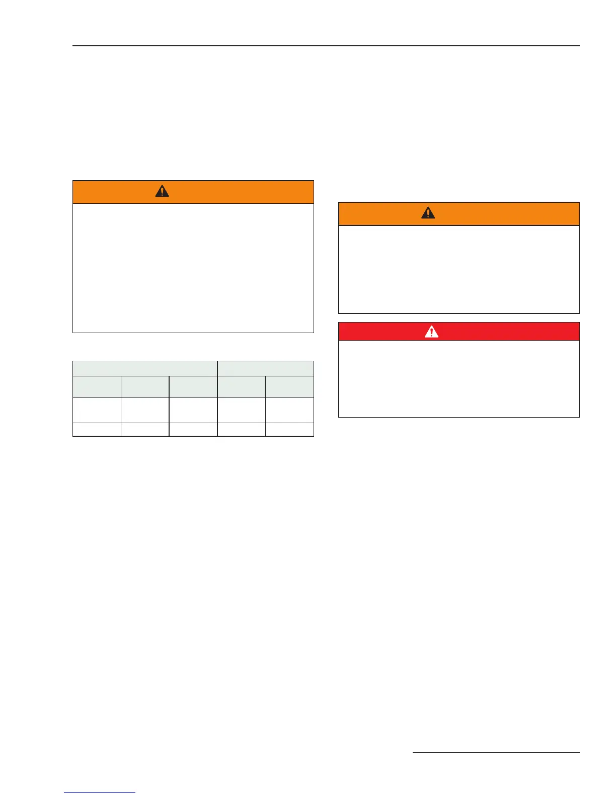
Table 1. Maximum Insulation Test Voltages
Vista SD Switchgear Rating, kV Withstand Test Voltage, kV
IEC IEEE
Impulse
(BIL)
Power
Frequency
①
Dc
②③
12 1 7. 5 95 31 42
24 29 125 45 62
① The power-frequency withstand test voltages listed in the table are
approximately 80% of the design values for new equipment.
② The dc withstand test voltages listed in the table are approximately
80% of the design values for new equipment.
③ Dc withstand test voltages are given for reference for those users per-
forming dc withstand tests. The presence of these values does not imply
a dc withstand rating or performance requirements for the switchgear.
A dc withstand design test is specified for new equipment because the
switchgear may be subjected to dc test voltage when connected to the
cable. The dc withstand test voltages listed in the table are approximately
equal to the ac test voltage.
Dc Cable Testing and Fault Locating
Dc testing of installed cables is performed to determine the
condition of the cables and to locate faults. Industry standards
such as IEEE 400, “IEEE Guide for Making High-Direct-Voltage
Tests on Power Cable Systems in the Field,” describe such
testing and should be referenced for selection of the test
procedures. Dc testing also includes cable “thumping” (the
sudden application of dc voltage from a large capacitor for
the purpose of fault locating), which causes transients and
voltage doubling at the end of the open cable. When the cables
are attached to the switchgear, the unit will also be subjected
to the dc test voltages.
WARNING
Aging, damage, or electrical or mechanical wear may
reduce the dc withstand capability of the switchgear.
Therefore, the dc test voltage must be selected such
that it does not exceed the withstand limits of the switch-
gear. Application of dc test voltage greater than the
withstand capability of the switchgear can result in a
flashover, injury, and equipment damage.
DANGER
Do not exceed the test voltages given in Table 1. Exceed-
ing the test voltages can cause a flashover of the isolating
gap or phase-to-phase insulation of the switchgear. This
can lead to a power-frequency fault in the gear of the
dc test source and result in severe personal injury of
death.
 Loading...