EasyManua.ls Logo

Sharp LC-24LE170I User Manual

Sharp LC-24LE170I
54 pages
To Next Page IconTo Next Page
To Previous Page IconTo Previous Page
Page #2 background image
LC-24LE170I
i
LC-90LE740X
Service Manual
SAFETY PRECAUTION
IMPORTANT SERVICE SAFETY PRECAUTION
WARNING
1. For continued safety, no modification of any circuit should be
attempted.
2. Disconnect AC power before servicing.
BEFORE RETURNING THE RECEIVER (Fire &
Shock Hazard)
Before returning the receiver to the user, perform the following
safety checks:
3. Inspect all lead dress to make certain that leads are not pinched,
and check that hardware is not lodged between the chassis and
other metal parts in the receiver.
4. Inspect all protective devices such as non-metallic control knobs,
insulation materials, cabinet backs, adjustment and compartment
covers or shields, isolation resistor-capacitor networks, mechanical
insulators, etc.
5. To be sure that no shock hazard exists, check for leakage current
in the following manner.
Plug the AC cord directly into a 110-240 volt AC outlet.
Using two clip leads, connect a 1.5k ohm, 10 watt resistor paral-
leled by a 0.15µF capacitor in series with all exposed metal cabinet
parts and a known earth ground, such as electrical conduit or elec-
trical ground connected to an earth ground.
Use an AC voltmeter having with 5000
ohm per volt, or higher, sen-
sitivity or measure the AC voltage drop across the resistor.
Connect the resistor connection to all exposed metal parts having a
return to the chassis (antenna, metal cabinet, screw heads, knobs
and control shafts, escutcheon, etc.) and measure the AC voltage
drop across the resistor.
All checks must be repeated with the AC cord plug connection
reversed. (If necessary, a nonpolarized adaptor plug must be used
only for the purpose of completing these checks.)
Any reading of 0.75 Vrms (this corresponds to 0.5 mA rms AC.) or
more is excessive and indicates a potential shock hazard which
must be corrected before returning the monitor to the owner.
///////////////////////////////////////////////////////////////////////////////////////////////////////////////////////////////////////////////////////////////////////////////////////////////////////////////////////////////////////////
SAFETY NOTICE
Many electrical and mechanical parts in LCD color television have
special safety-related characteristics.
These characteristics are often not evident from visual inspection, nor
can protection afforded by them be necessarily increased by using
replacem
ent components rated for higher voltage, wattage, etc.
Replacement parts which have these special safety characteristics are
identified in this manual; electrical components having such features
are identified by " " and shaded areas in the Replacement Parts List
and Schematic Diagrams.
For continued protection, replacement parts must be identical to those
used in the original circuit.
The use of a substitute replacement parts which do not have the same
safety characteristics as the factory recommended replacement parts
shown in this service manual, may create shock, fire or other hazards.
///////////////////////////////////////////////////////////////////////////////////////////////////////////////////////////////////////////////////////////////////////////////////////////////////////////////////////////////////////////
Service work should be performed only by qualified service technicians who are thoroughly familiar with all safety checks and the
servicing guidelines which follow:
CAUTION : FOR C ONTINUE D PROTECTION
AGAINST A RISK OF FIRE REPLACE ONLY WITH
SAME TYPE FUSE.
F7001 (250V 6.3A)
DVM
AC SCALE
1.5k ohm
10W
TO EXPOSED
METAL PARTS
CONNECT TO
KNOWN EARTH
GROUND
0.15
µ
F
TEST PROBE
Question and Answer IconNeed help?

Do you have a question about the Sharp LC-24LE170I and is the answer not in the manual?

Sharp LC-24LE170I Specifications

General IconGeneral
Screen Size24 inches
Resolution1366 x 768
Display TypeLED
HDMI Ports2
USB Ports1
Weight5.2 kg
Aspect Ratio16:9
Refresh Rate50 Hz
Sound Output10 W
Backlight TypeLED

Summary

Safety Precautions

Important Service Safety Precaution

Critical safety measures for technicians during service.

Before Returning the Receiver (Fire & Shock Hazard)

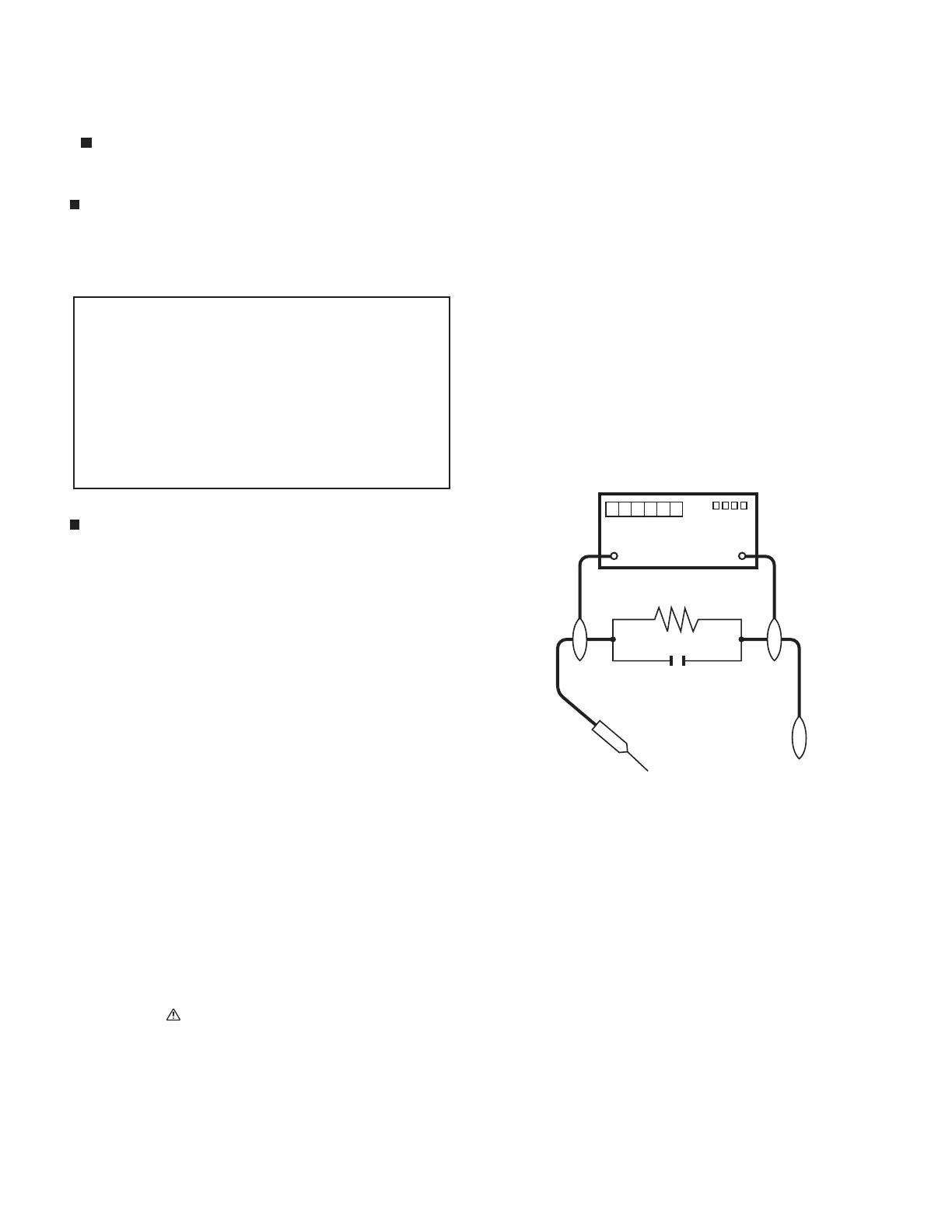
Post-service safety checks to prevent fire and shock hazards.

Safety Notice

General safety advice regarding part replacement and characteristics.

Precautions for Using Lead-Free Solder

Detailed instructions on using lead-free solder and its implications.

Chapter 1: Outline

[1] Outline

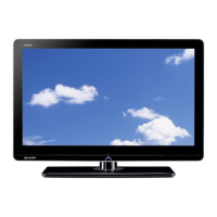
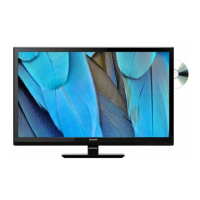
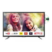
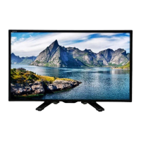
General overview of the TV's design and purpose.

Chapter 2: Specifications

[1] Specifications

Detailed technical specifications of the LC-24LE1701 model.

Chapter 3: Operation Manual

[1] Operation Manual

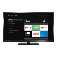
Instructions for using the TV's features and functions.

Remote Control Unit

Description and function of each button on the remote control.

Attaching the Stand

Attaching the Stand

Step-by-step guide for assembling the TV stand.

Chapter 4: Dimensions

[1] Dimensions

Physical measurements and mounting information for the TV.

Chapter 5: Removing Major Parts

[1] Removing of Major Parts

Procedures for disassembling and removing key internal components.

1. Removing Speaker L/R and PWB Chassis.

Steps to remove speakers and the main Printed Wiring Board assembly.

1. Removing of the LCD Panel Module

Procedures for safely removing the LCD panel module from the TV.

Chapter 6: Adjustment

[1] Adjustment Procedure

Steps to enter and navigate the TV's adjustment mode.

3. Software Upgrading

Process for updating the TV's firmware via USB.

1. Signal Adjustment

Procedures for calibrating signal inputs for optimal picture quality.

B. White Balance Adjustment

Detailed procedure for white balance calibration.

Chapter 7: Troubleshooting Table

[1] Troubleshooting Table

Diagnostic guide for identifying and resolving common TV issues.

Chapter 8: Overall Wiring / System Block Diagram

[1] System Block Diagram

High-level overview of the TV's functional blocks and interconnections.

Chapter 9: Printed Wiring Board Assemblies

[1] Main & Power Unit

Component layout and identification for the Main & Power PWB.

[2] LED RC Unit

Component layout and identification for the LED RC PWB.

Chapter 10: Schematic Diagram

[1] Description of Schematic Diagram

Explanation of schematic symbols and measurement conditions.

[2] Main Unit

Detailed electrical schematic for the main circuit board.

[3] LED RC Unit

Detailed electrical schematic for the LED RC circuit board.

[4] POWER Unit

Detailed electrical schematic for the power supply circuit board.

SHARP PARTS GUIDE

[1] PRINTED WIRING BOARD ASSEMBLIES

Part numbers and descriptions for PWBs.

[3] MAIN/POWER UNIT

Part numbers and descriptions for the Main/Power unit components.

Related product manuals