Operating Instructions
LMS1xx Laser Measurement Sensors
Electrical installation
8012471/ZN27/2017-06-09 © SICK AG · Germany · All rights reserved · Subject to change without notice 73
Chapter 6
6.4 Perform electrical installation on the LMS1xx
Lay all cables such that there is no risk of tripping and all cables are protected against
damage.
6.4.1 Equipment
Tool set
Digital multimeter (current/voltage measurement)
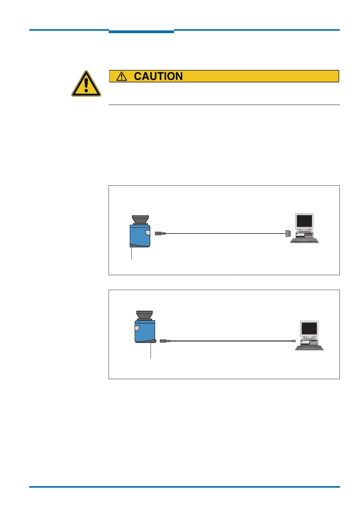
6.4.2 Connecting the AUX or the Ethernet interface to the PC
Pre-assembled cables are available to configure the LMS1xx via the serial auxiliary interface
or via the Ethernet interface.
Fig. 46: Connecting the auxiliary interface (RS-232) to the PC
Fig. 47: Connecting the Ethernet interface to the PC
DC 24 V
Male connector
Female connector
DSub
9 pin
M8 , 4-pin
Part no. 6021195, 2 m
Part no. 2027649, 10 m
LMS1xx
PC
LMS1xx
DC 24 V
M12 , 4- pin,
D-coded
RJ45,
8-pin
Male connector
Part no. 6034415, 5 m
Part no. 6030928, 10 m
Part no. 6036158, 20 m
Male connector
PC

 Loading...