Operating Instructions
LMS1xx Laser Measurement Sensors
Electrical installation
8012471/ZN27/2017-06-09 © SICK AG · Germany · All rights reserved · Subject to change without notice 77
Chapter 6
6.4.5 Wiring of switching inputs and outputs on the LMS1xx
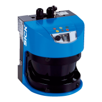
Connecting switching inputs referred to a potential (power supply voltage)
Fig. 48: Connecting switching input, e.g. IN1, referred to a potential
Important The switching inputs require a switching voltage of at least DC 11 V. For this reason the
supply voltage must be at least DC 11 V.
Connecting switching inputs as floating
Fig. 49: Connecting switching input, e.g. IN1, as floating
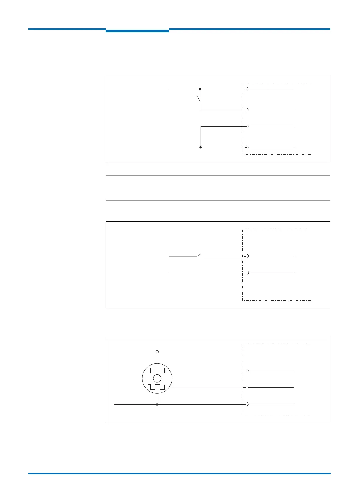
Wiring encoder inputs
Fig. 50: Wiring encoder inputs
LMS1xx
IN1
GND IN1
GND
V
S
= DC 11 V … 30 V
External switch
LMS1xx
IN1
GND IN1
External signal source
V
in
= DC 11 V … 30 V
LMS1xx
INC1 A
INC1 B
GND
V
S
encoder
GND encoder
0°
90°

 Loading...