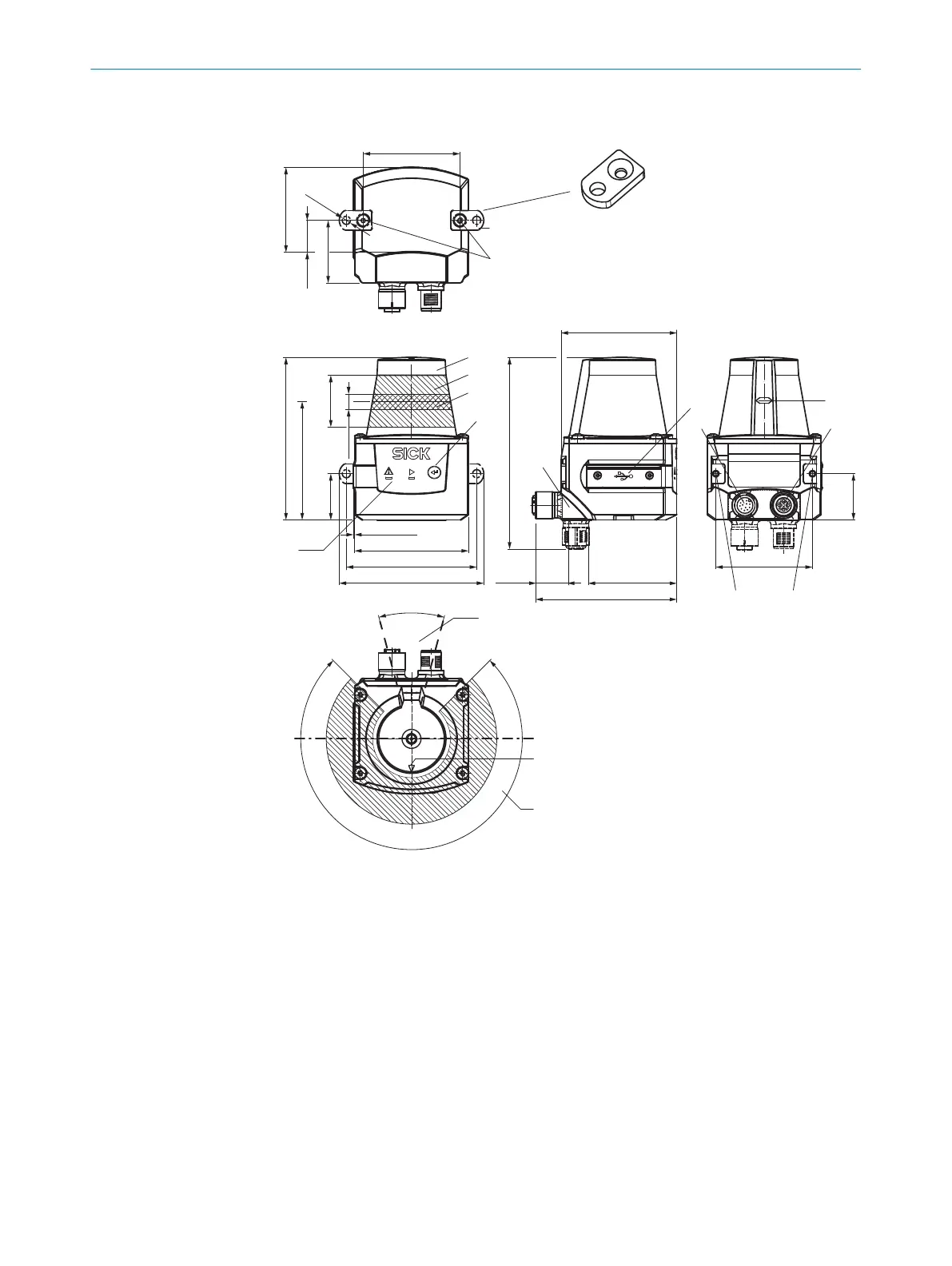
3.2 Setup and dimensions
4
5
3
ß
7
9
à
2 2
225°
‒45°
180°0°
ä
ã
85.75 (3.38)
27.3
[24.4
62.46 (2.46)
60 (2.30)
0.7 (0.03)
[68.8 (2.71)]
[76.25 (3.00)]
61 (2.40)
46.71 (1.84)
74.39 (2.93)
101.12 (3.98)
17.37
(0.68)
51 (2.01)
30°
90°
6
á
8
â
2
1
2 x
51 (2.01)
44.79 (1.76)
16.79
(0.66)
33 (1.3)
[Ø 4.3
(0.17)
]
(0.96)]
(1.07)
8
(0.31)
24.4
(0.96)
Figure 1: Structure and dimensions, unit: mm (inch), decimal separator: period
1
2x fastening clip with M3 x 5 mm countersunk screw, self-locking (included in scope of
delivery)
2
M3 threaded mounting hole, 2.8 mm deep (blind hole thread), max. tightening torque
0.8 Nm
3
Optics cover
4
Receiving range (light inlet)
5
Transmission range (light emission)
6
"Teach-in” pushbutton
7
Red and green LED (status indicators)
8
Swivel connector unit with electrical connections
9
Micro USB port, behind the black plaster cover (“Aux interface” connection for configura‐
tion with PC)
ß
Voltage supply connection, 5-pin M12 female connector
PRODUCT DESCRIPTION 3
8025144//2021-07-21 | SICK O P E R A T I N G I N S T R U C T I O N S | TiM55x/56x/57x/58x
11
Subject to change without notice
 Loading...