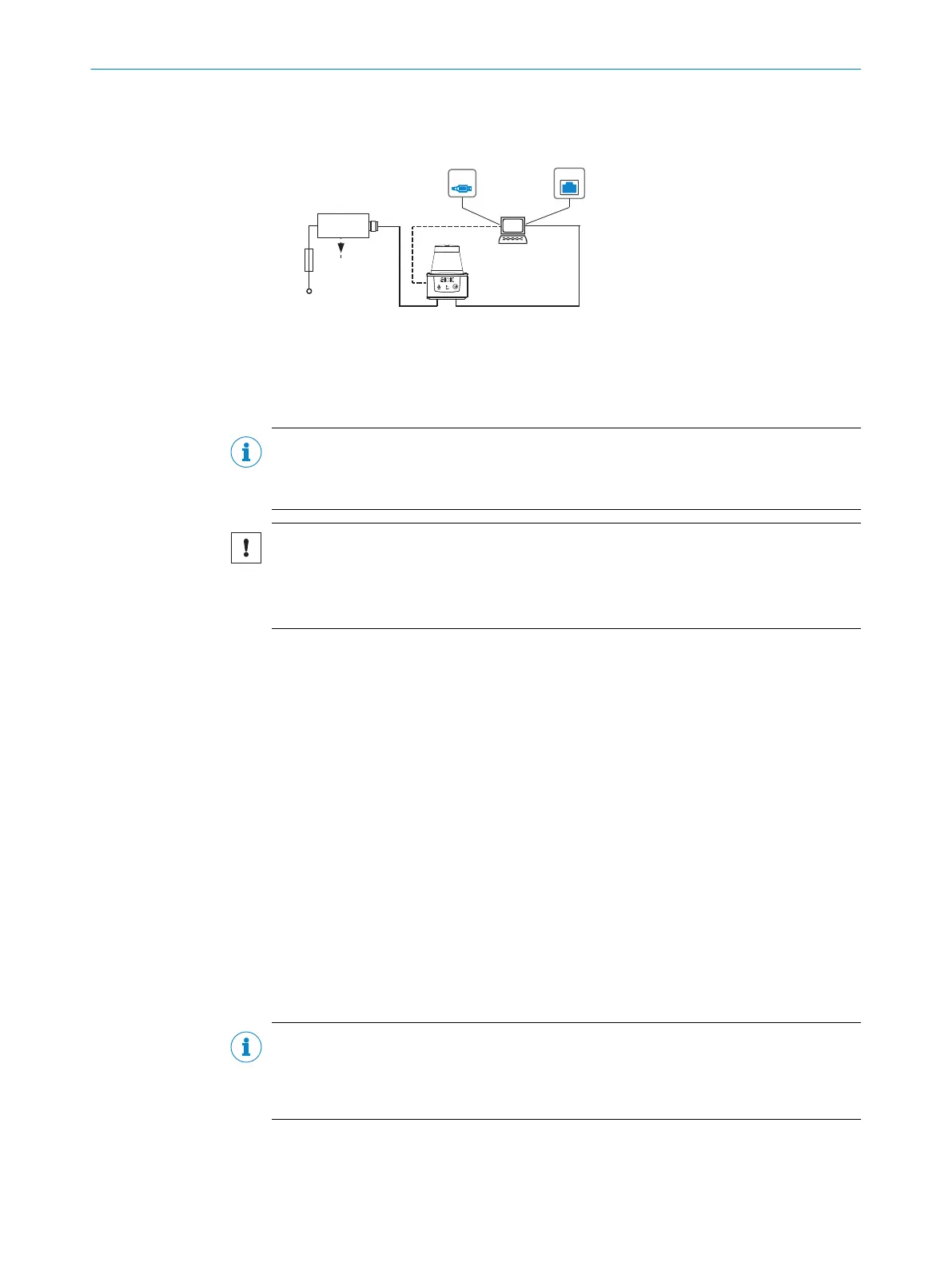
6.2 Electrical block diagram for commissioning
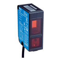
TiMxxx-20xxxxx
SOPASSOPAS
„Power/Out“
„USB 2.0“
Configuration
Diagnosis
TiM
Connection
box
USBUSB
Driver for request of
measurement values
and further data
processing
SYNC/
Device Ready
„Ethernet“
EthernetEthernet
DC 9 ... 28 V
Fuse
0,8A/T
Figure 22: “Power, I/O” connection: With M12 male connector, 5-pin, A-coded; “Ethernet” con‐
nection: With M12 female connector, 4-pin, D-coded
6.3 Wiring instructions
NOTE
Pre-assembled cables can be found online at:
•
www.sick.com/TiM5xx
NOTICE
Faults during operation and device or system defects!
Incorrect wiring may result in operational faults and defects.
■
Follow the wiring notes precisely.
The protection class stated in the technical data is achieved only with screwed plug
connectors or protective caps.
Protect the device from dust and moisture when the plastic USB cover is open.
The USB interface is only for parameterization. Remove the USB cable for problem-free
operation of the device.
All circuits connected to the device must be configured as SELV or PELV circuits. SELV =
safety extra-low voltage, PELV = protective extra-low voltage.
Protect the device with an external 0.8 A slow-blow fuse at the beginning of the supply
cable.
Connect the connecting cables in a de-energized state. Do not switch on the supply volt‐
age until installation is complete and all connection work on the device and controller
has been finished.
Wire cross-sections in the supply cable from the customer’s power system must be
implemented in accordance with the applicable standards.
6.4 Connection diagram
NOTE
The recommended connecting cables and their associated technical data can be found
online at:
www.sick.com/TiM5xx
6 ELECTRICAL INSTALLATION
28
O P E R A T I N G I N S T R U C T I O N S | TiM55x/56x/57x/58x 8025144//2021-07-21 | SICK
Subject to change without notice

 Loading...