6 Electrical installation
6.1 Prerequisites for safe operation of the device
WARNING
Risk of injury and damage caused by electrical current!
As a result of equipotential bonding currents between the device and other grounded
devices in the system, faulty grounding of the device can give rise to the following
dangers and faults:
■
Dangerous voltages are applied to the metal housings.
■
Devices will behave incorrectly or be destroyed.
■
Cable shielding will be damaged by overheating and cause cable fires.
Remedial measures
■
Only skilled electricians should be permitted to carry out work on the electrical
system.
■
If the cable insulation is damaged, disconnect the voltage supply immediately and
have the damage repaired.
■
Ensure that the ground potential is the same at all grounding points.
■
Where local conditions do not meet the requirements for a safe earthing method,
take appropriate measures (e.g., ensuring low-impedance and current-carrying
equipotential bonding).
The device is connected to the peripheral devices (voltage supply, any local trigger
sensor(s), system controller) via shielded cables. The cable shield – for the data
cable, for example – rests against the metal housing of the device. The device can
be grounded through the cable shield or through a blind tapped hole in the housing,
for example.
If the peripheral devices have metal housings and the cable shields are also in contact
with their housings, it is assumed that all devices involved in the installation have the
same ground potential.
This is achieved by complying with the following conditions:
■
Mounting the devices on conductive metal surfaces
■
Correctly grounding the devices and metal surfaces in the system
■
If necessary: low-impedance and current-carrying equipotential bonding between
areas with different ground potentials
SICK
Device
7 46
Power Supply
U
= 8
= 9
1 2 3
I
5
System
Controller
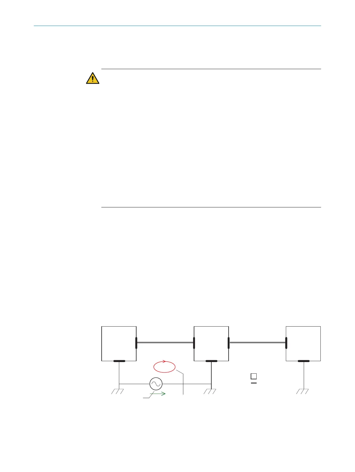
Figure 19: Example: Occurrence of equipotential bonding currents in the system configuration
1
System controller
2
Device
3
Voltage supply
ELECTRICAL INSTALLATION 6
8025144//2021-07-21 | SICK O P E R A T I N G I N S T R U C T I O N S | TiM55x/56x/57x/58x
25
Subject to change without notice
 Loading...