Slave Diagnostics
126
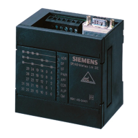
DP/AS-Interface Link 20E
Release 11/2002
C79000-G8976-C138–04
4.1 Overview
Notice
Remember that the DP/AS-i Link 20E only signals errors on the AS-Interface when
the DP/AS-i Link 20E is operating in the protected mode and when the diagnostic
interrupt is enabled in the DP configuration.
In SIMATIC S7, the default is “diagnostic interrupt deactivated”.
Notice
If the AS-i voltage drops below 14 V, then no DP data exchange is possible due to
the lack of power supply. This means that no diagnostic message can be created
to signal that the AS-i power supply is too low. The DP master recognizes that the
DP/AS-i Link 20E module has failed and indicates this problem to its user
program.
Access Mechanism
Read the manual of your DP master to find out the mechanisms you can use on
the DP master to access diagnostic information.
The following sections explain the content of the slave diagnostic information.
Structure of Slave Diagnostic Information
Slave diagnostic information on the DP/AS-i Link 20E module uses 28 bytes and is
structured as follows:
Byte 0
Byte 1 Station status 1 to 3
Byte 2
Byte 3 DP master PROFIBUS address
Byte 4 High byte vendor ID
Byte 5 Low byte vendor ID
Byte 6
Byte 7 ID-related diagnostic information
Byte 8
Byte 9
Byte 10
Byte 11
Byte 12
Byte 13

 Loading...


